
Method, system and apparatus for fault detection in line protection for power transmission system

A line protection and fault detection technology, applied in the field of power transmission, to achieve the effect of reducing the sampling rate, realizing line protection, and ultra-fast line protection

Pending Publication Date: 2018-10-23
HITACHI ENERGY SWITZERLAND AG
View PDF5 Cites 8 Cited by
  • Summary
  • Abstract
  • Description
  • Claims
  • Application Information

AI Technical Summary

Problems solved by technology

[0006] Various embodiments of the present disclosure mainly aim to provide a solution for fault detection in line protection of electric power transmission system, so as to solve or at least partially alleviate at least some of the problems in the prior art

Method used


Image

  • Method, system and apparatus for fault detection in line protection for power transmission system
  • Method, system and apparatus for fault detection in line protection for power transmission system
  • Method, system and apparatus for fault detection in line protection for power transmission system

Examples


Embodiment Construction

[0031]Hereinafter, the principle and spirit of the present disclosure will be described with reference to the illustrated embodiments. It should be understood that all these embodiments are given only for those skilled in the art to better understand and further practice the present disclosure, rather than to limit the scope of the present disclosure. For example, features illustrated or described as part of one embodiment can be used with another embodiment to yield a still further embodiment. In the interest of clarity, not all features of an actual implementation are described in this specification.

[0032] References in the specification to "one embodiment," "an embodiment," "example embodiment," etc. mean that the described embodiments may include a particular feature, structure, or characteristic but that each embodiment does not necessarily include the particular feature, structure, or characteristic. structure or property. Moreover, such terms are not necessarily re...


PUM


Abstract

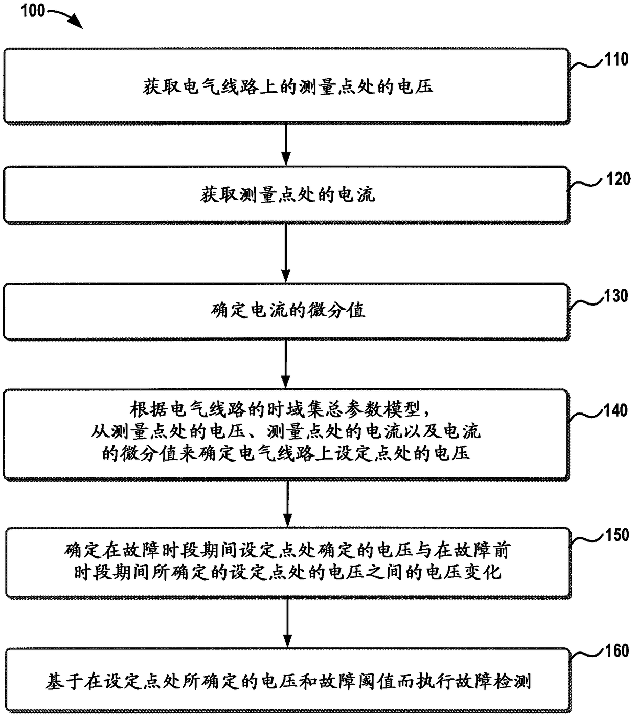
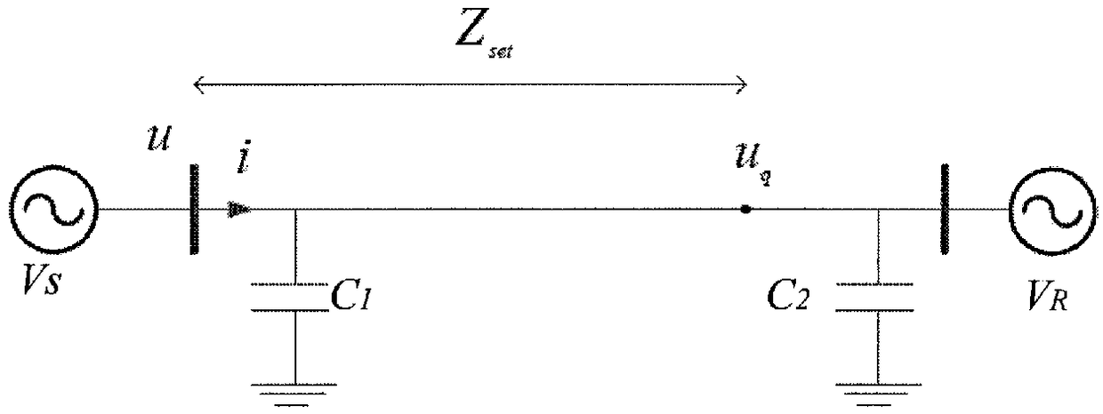
A method, system and apparatus of fault detection in line protection for a power transmission system. A voltage (u) at a measurement point on an electrical line is obtained. The measurement point is apoint at which a protection device for the line protection is installed. A current (i) at the measurement point is further obtained and a differential value of the current is determined. Then, a voltage (u q) at a setting point on the electrical line is determined from the voltage (u) at the measurement point, the current (i) at the measurement point and the differential value of the current (i)according to a time domain lumped parameter model for the electrical line. The voltage change between the determined voltage at the setting point during the fault period and a voltage at the setting point determined during a pre-fault period can be further determined. The fault detection can be performed based on the determined voltage change and a fault threshold. It can ensure voltage determination accuracy and detection reliability with a low sampling rate. Moreover, the solution can work right after the fault inception, almost no waiting time is required, and thus it may achieve a super-fast line protection.

Description

technical field [0001] The non-limiting and exemplary embodiments of the present disclosure relate generally to the field of power transmission, and more particularly to a method, system and apparatus for fault detection in line protection of power transmission systems. Background technique [0002] This section introduces aspects that may contribute to a better understanding of the disclosure. Accordingly, the statements in this section should be read accordingly and should not be construed as an admission that what is or is not prior art. [0003] Distance protection is one of line protection techniques that determines the distance between a fault point and a point where a protection device is installed and determines the time of action based on the determined distance. For both technical and commercial reasons, distance protection is one of the most important protections for extra high voltage / extra high voltage (EHV / UHV) transmission line systems. For line distance pro...

Claims


Application Information

Patent Timeline
Patent Type & Authority Applications(China)
IPC IPC(8): G01R31/08G01R31/58
CPCH02H3/38G01R31/08G01R31/088G01R31/085H02H3/40G01R31/52G01R31/58H02H1/0007
Inventor 刘凯李幼仪王建平
Owner HITACHI ENERGY SWITZERLAND AG
Learn More