Orthopedic fixing device
A fixation device and orthopedic technology, applied in the field of medical tools, can solve problems such as inability to guarantee, and achieve the effects of guaranteed success rate, convenient use, and simple operation
- Summary
- Abstract
- Description
- Claims
- Application Information
AI Technical Summary
Problems solved by technology
Method used
Image
Examples
specific Embodiment approach 1
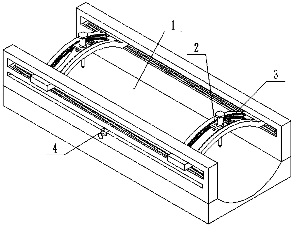
[0025] The fixed connection mentioned in this device refers to fixing by welding, screw fixing, etc., and different fixing methods are used in combination with different use environments; the rotating connection refers to drying the bearing on the shaft, the shaft or A circlip groove is arranged on the shaft hole, and the axial fixation of the bearing is realized by inserting the circlip into the circlip groove, and the rotation is realized; Sliding inside is used to connect; the hinged joint refers to a connection method that moves on connecting parts such as hinges, pin shafts, and short shafts; Or the tip makes the upsetting part or the tip makes the upsetting head into a head, concentrate all efforts, and connect the metal objects together with rivets; the required seals are all sealed by sealing rings or O-rings.
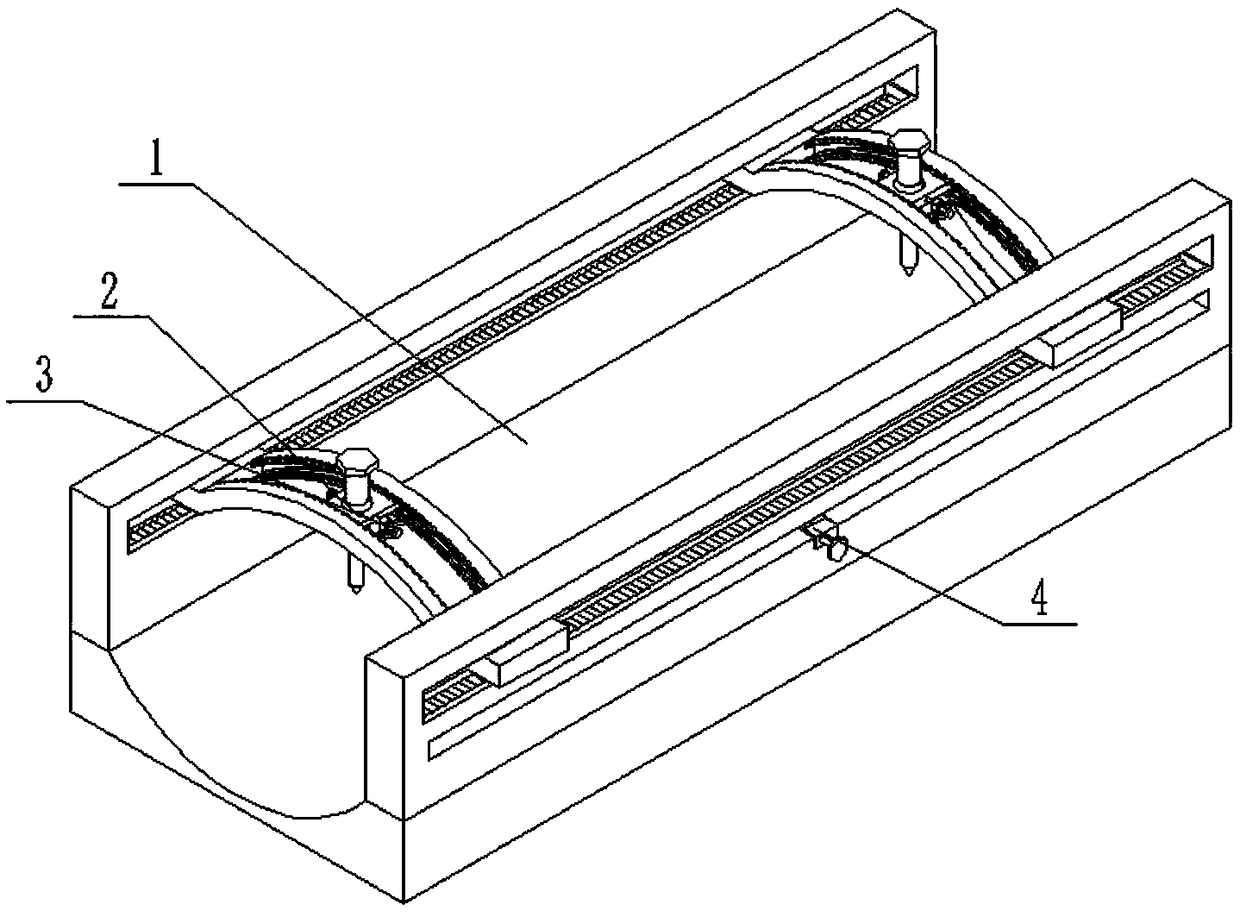
[0026] Such as Figure 1 to Figure 11 As shown, an orthopedic fixation device includes a limb fixation platform 1, a drilling fixing device 2, a left and righ...
specific Embodiment approach 2
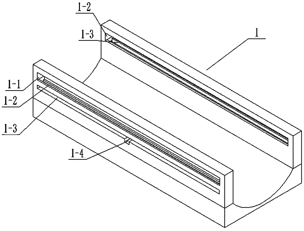
[0027] Such as Figure 1 to Figure 11 As shown, this embodiment will further describe Embodiment 1. The limb fixation platform 1 includes a limb fixation seat 1-1, two pulley slides 1-2, two rack placement grooves 1-3, and two tooth racks. Bar driving groove 1-4 and two fixing grooves 1-5, two pulley slideways 1-2 run through the front and back ends of limb fixing seat 1-1 respectively, and two rack driving grooves 1-4 are respectively arranged on through At the front and rear ends of the limb fixing seat 1-1, the two rack placement grooves 1-3 are respectively arranged on the lower ends of the two pulley slideways 1-2, and the upper ends of the two rack placement grooves 1-3 are respectively connected to two slide rails. The wheel slideway 1-2, the lower ends of the two rack placement grooves 1-3 are respectively connected to the two rack driving grooves 1-4, and the two fixing grooves 1-5 are respectively arranged in the middle of the two rack driving grooves 1-4. end.
specific Embodiment approach 3
[0028] Such as Figure 1 to Figure 11As shown, this embodiment will further describe the second embodiment. The drilling fixture 2 includes a sliding arc block 2-1, two pulley sliding grooves 2-2, two pulley shafts 2-3, two Pulley 2-4, mid-end groove 2-5, center block chute 2-6, left and right fixed slots 2-7, center block 2-8, drilling tap 2-9, center ball groove 2-10, center ball Shell 2-11, fastening bolt 2-12, a plurality of sliding ball grooves 2-13 and a plurality of small steel balls 2-14, two pulley sliding grooves 2-2 run through the left and right sides of the sliding arc block 2-1 up and down respectively. Two pulley rotating shafts 2-3 are respectively fixedly connected in two pulley sliding grooves 2-2, and two pulleys 2-4 are respectively rotated and connected to two pulley rotating shafts 2-3, and two pulley slideways 1-2 The middle end is tooth-shaped, and the two pulleys 2-4 are slidably connected to the two pulley slides 1-2 respectively. The middle end groo...
PUM
 Abstract
Description
Claims
Application Information
 - R&D
- Intellectual Property
- Life Sciences
- Materials
- Tech Scout
- Unparalleled Data Quality
- Higher Quality Content
- 60% Fewer Hallucinations
Browse by: Latest US Patents, China's latest patents, Technical Efficacy Thesaurus, Application Domain, Technology Topic, Popular Technical Reports.
© 2025 PatSnap. All rights reserved.Legal|Privacy policy|Modern Slavery Act Transparency Statement|Sitemap|About US| Contact US: help@patsnap.com


