Orthopedic fixation device

A fixation device and orthopedic technology, applied in the field of medical tools, can solve problems such as inability to guarantee, achieve the effects of guaranteeing success rate, avoiding drilling deviation, and being convenient to use

Inactive Publication Date: 2020-04-28
李宝京 +2
View PDF1 Cites 0 Cited by
  • Summary
  • Abstract
  • Description
  • Claims
  • Application Information

AI Technical Summary

Problems solved by technology

However, this equipment cannot guarantee the success rate of bone screw drilling in the process of osteosynthesis of fractures.

Method used


Image

  • Orthopedic fixation device
  • Orthopedic fixation device
  • Orthopedic fixation device

Examples


specific Embodiment approach 1

[0026] The fixed connection mentioned in this device refers to fixing by welding, screw fixing, etc., and different fixing methods are used in combination with different use environments; the rotating connection refers to drying the bearing on the shaft, the shaft or A circlip groove is arranged on the shaft hole, and the axial fixation of the bearing is realized by inserting the circlip into the circlip groove, and the rotation is realized; Sliding inside is used to connect; the hinged joint refers to a connection method that moves on connecting parts such as hinges, pin shafts, and short shafts; Or the tip makes the upsetting part or the tip makes the upsetting head into a head, concentrate all efforts, and connect the metal objects together with rivets; the required seals are all sealed by sealing rings or O-rings.

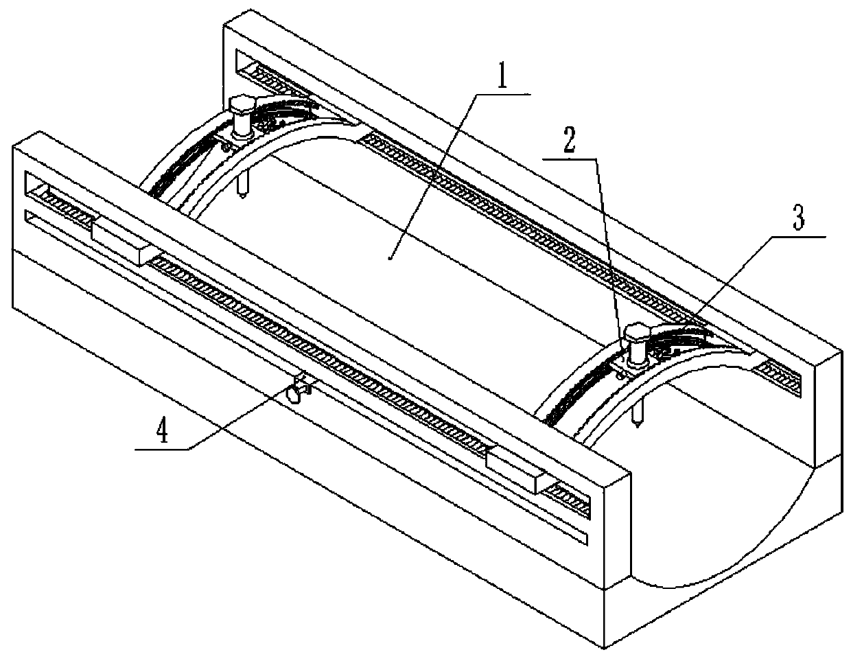
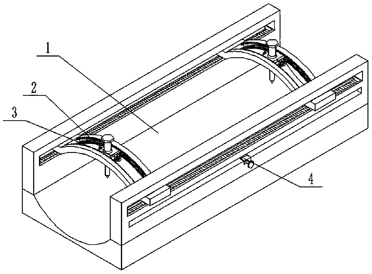
[0027] Such as Figure 1 to Figure 11 As shown, an orthopedic fixation device includes a limb fixation platform 1, a drilling fixing device 2, a left and righ...

specific Embodiment approach 2

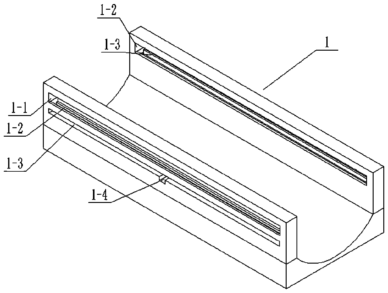
[0029] Such as Figure 1 to Figure 11 As shown, this embodiment will further describe Embodiment 1. The limb fixation platform 1 includes a limb fixation seat 1-1, two pulley slides 1-2, two rack placement grooves 1-3, and two tooth racks. Bar driving groove 1-4 and two fixing grooves 1-5, two pulley slideways 1-2 run through the front and back ends of limb fixing seat 1-1 respectively, and two rack driving grooves 1-4 are respectively arranged on through At the front and rear ends of the limb fixing seat 1-1, the two rack placement grooves 1-3 are respectively arranged on the lower ends of the two pulley slideways 1-2, and the upper ends of the two rack placement grooves 1-3 are respectively connected with two slide rails. The wheel slideway 1-2, the lower ends of the two rack placement grooves 1-3 are respectively connected to the two rack driving grooves 1-4, and the two fixing grooves 1-5 are respectively arranged in the middle of the two rack driving grooves 1-4. end.

specific Embodiment approach 3

[0031] Such as Figure 1 to Figure 11As shown, this embodiment will further describe the second embodiment. The drilling fixture 2 includes a sliding arc block 2-1, two pulley sliding grooves 2-2, two pulley shafts 2-3, two Pulley 2-4, mid-end groove 2-5, center block chute 2-6, left and right fixed slots 2-7, center block 2-8, drilling tap 2-9, center ball groove 2-10, center ball Shell 2-11, fastening bolt 2-12, a plurality of sliding ball grooves 2-13 and a plurality of small steel balls 2-14, two pulley sliding grooves 2-2 run through the left and right sides of the sliding arc block 2-1 up and down respectively. Two pulley rotating shafts 2-3 are respectively fixedly connected in two pulley sliding grooves 2-2, and two pulleys 2-4 are respectively rotated and connected to two pulley rotating shafts 2-3, and two pulley slideways 1-2 The middle end is tooth-shaped, and the two pulleys 2-4 are slidably connected to the two pulley slides 1-2 respectively. The middle end groo...


PUM


Abstract

The invention relates to the field of medical tools, in particular to an orthopedic fixing device which comprises a limb fixing table, a drilling hole fixing device, a bilaterally movable fixing device and two pulley fixing devices. The left end and the right end of the drilling hole fixing device are slidably connected at the left end and the right end of the limb fixing table, the bilaterally movable fixing device is fixedly connected in the drilling hole fixing device, the two pulley fixing devices are in clearance fit with the left end and the right end of the limb fixing table, and the upper ends of the two pulley fixing devices are engaged with the left end and the right end of the drilling hole fixing device. The orthopedic fixing device has the advantages that fracture bones can bedrilled when fracture fixation is implemented, multi-angle adjustment of a drilling device is guaranteed, multi-angle and all-directional drilling of the bones can be achieved by combining fracture positions of patients, bone nails are drilled into the bones, and the drilling success rate is guaranteed.

Description

technical field [0001] The invention relates to the field of medical tools, in particular to an orthopedic fixation device. Background technique [0002] Most of the work in orthopedics is to use bone nails and brackets to perform fracture fixation on broken or fractured bones. Patent No. CN201510126465.6 discloses an auxiliary fixation device for fracture surgery, which belongs to the technical field of medical devices. The auxiliary fixation device for fracture operation of the present invention comprises a main body, a rear track base and a front track base, a power control box is arranged on the left side of the main body, a vent is arranged on the front side of the power control box, and a louver blade rotating shaft is arranged on the vent. The louver blade is arranged on the fan blade rotating shaft, the louver blade opening and closing runner installation groove is arranged on the right side of the air vent, and the louver blade opening and closing runner is provide...

Claims


Application Information

Patent Timeline
Patent Type & Authority Patents(China)
IPC IPC(8): A61B90/14A61B17/16
CPCA61B17/16A61B90/14
Inventor 李宝京王贵君张明建刘英秀
Owner 李宝京
Why Eureka
Try Eureka