Pulley gear for heel as well as roller skate and roller shoe with pulley gear

A pulley and heel technology, which is applied to footwear, skating, shoe soles, etc., can solve problems such as high manufacturing precision requirements, shedding necrosis, and potential safety hazards, and achieves a combination that ensures stability, reduces impact side effects, and has reliable and stable performance. Effect

Active Publication Date: 2018-10-26
晋江腾强鞋材有限公司
View PDF6 Cites 0 Cited by
  • Summary
  • Abstract
  • Description
  • Claims
  • Application Information

AI Technical Summary

Problems solved by technology

[0002] With the development of society and the improvement of living standards, people are constantly pursuing sports that are both stimulating and entertaining, and violent walking shoes have emerged as the times require, but the existing violent walking shoes have the following deficiencies in the use process: one is Because the rollers need to be disassembled frequently, the card slots are deformed and worn, resulting in loose wheel shafts. If not handled in time, they will suddenly fall off and become necrotic during high-speed gliding, causing the skater to fall, posing a serious safety hazard
The second is that it is inconvenient to install and disassemble the rollers, and it must be completed with the help of disassembly tools
[0004] However, in the actual production and use process, the applicant found that: 1. To prevent the pulley assembly from floating up and down when it is in use, the height of the space between the second end of the U-shaped stop bar and the cover is required to match the pulley shaft The diameter of this place requires relatively high manufacturing accuracy, and the installation position of the second end of the U-shaped bar is also required to be high during assembly, and it cannot be too high or low, otherwise the height cannot be guaranteed even if the dimensional accuracy meets the standard Matching the diameter of the pulley shaft; 2. There is a gap between the two ends of the pulley shaft of the pulley assembly and the side wall of the wheel groove to ensure the normal rotation of the pulley body, and the switch of the pulley assembly from the retracted state to the downward convex state is to remove the slip. The blocking of the cover is completed by the push-down force of the first compression spring. In this way, the cover at the bottom opening of the communication groove is mainly used to receive the impact and limit the pulley shaft. The combination strength of the cover is required to be high, and it has been used for a long time. If you do not pay attention to maintenance, it may cause the cover to fall off and cause an accident

Method used


Image

  • Pulley gear for heel as well as roller skate and roller shoe with pulley gear
  • Pulley gear for heel as well as roller skate and roller shoe with pulley gear
  • Pulley gear for heel as well as roller skate and roller shoe with pulley gear

Examples


Embodiment 1

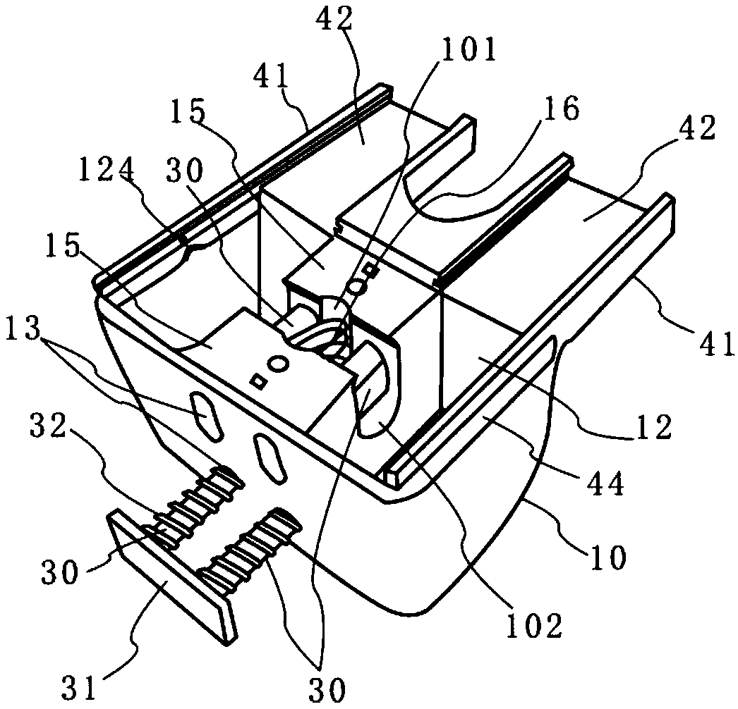
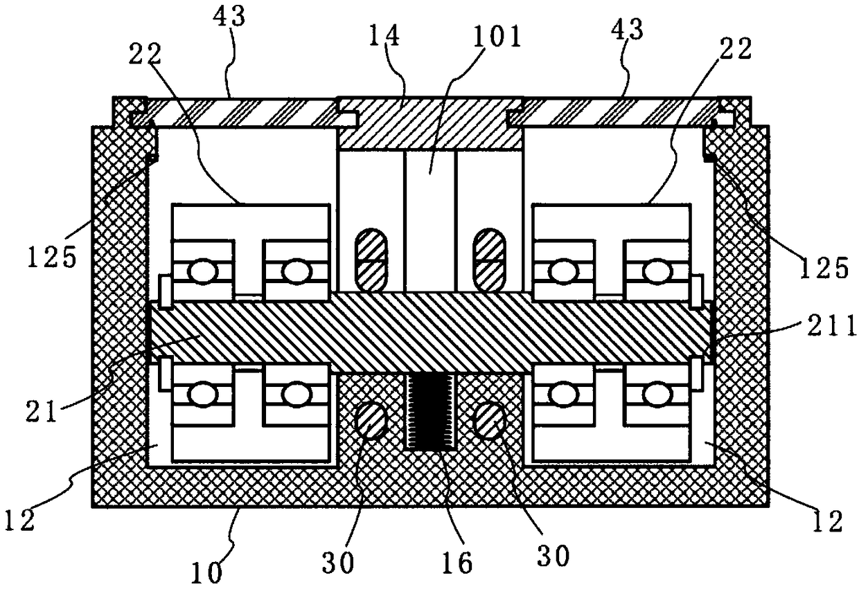
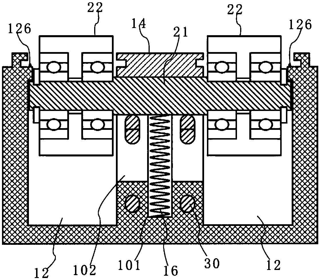
[0041] like Figure 1-8 As shown, the present embodiment provides a pulley device for a heel, and the pulley device 100 includes a pulley seat 10 , a pulley assembly 20 and two U-shaped blocking bars 30 .

[0042] In this embodiment, the pulley assembly 20 includes a pulley shaft 21 and two pulley bodies 22 respectively axially fixed and circumferentially rotatable arranged on the pulley shaft 21, wherein the axial ends of the pulley shaft 21 Each has a reduced diameter ring 211 and an enlarged diameter section 212 in the axial middle, and the axial length between the end of the expanded diameter section 212 and the reduced diameter ring 211 on the same side is equivalent to the axial width of the pulley body 22 . The central shaft hole of the pulley body 22 is divided into two installation cavities by a spacer, and rolling bearings are respectively pressed in each installation cavity. The rolling bearing abuts against the snap spring 213 fixed in the diameter reducing ring 2...

Embodiment 2

[0054] like Figure 1-10 As shown, this embodiment provides a walking shoe, including a sole body 200 and the pulley device 100 described in the first embodiment above, the pulley device 100 is installed on the heel of the sole body 200, and the bottom surface of the cover 14 On the same level as the bottom surface of the sole body 200, the rear side of the sole body 200 is provided with a mounting hole and a pressing block 201 movably inserted in the mounting hole, and the pressing block 201 is connected with the connecting plate 31, specifically The pressing block 201 is composed of a pressing part movably penetrated in the mounting hole and a limiting part connected to the front end of the pressing part and unable to pass through the mounting hole. The limiting part is connected with the connecting plate 31, and by pressing the The pressing block 201 can make the U-shaped bar 30 move backward to open the communication slot to facilitate the adjustment of the pulley assembly...

Embodiment 3

[0056] like Figure 1-8 , 11-14, this embodiment provides a roller skate, including a sole body 200, a front wheel device 500 and the pulley device 100 described in the first embodiment above.

[0057] The pulley device 100 is installed on the heel of the sole body 200, and the bottom surface of the cover 14 is on the same level as the bottom surface of the sole body 200. The rear side of the sole body 200 is provided with a mounting hole and is movably inserted in the mounting hole. The pressing block 201 inside, the pressing block 201 is connected with the connecting plate 31, specifically, the pressing block 201 is formed by a pressing part which is movable through the mounting hole and connected to the front end of the pressing part and cannot pass through the mounting hole. The limiting part is composed of a limiting part, the limiting part is connected with the connecting plate 31, and the U-shaped bar 30 can be moved backward by pressing the pressing block 201 to open t...


PUM


Abstract

The invention relates to a pulley gear for a heel. The pulley gear comprises a pulley seat, a pulley assembly, a blocking cover and two U-shaped stop levers, wherein two wheel grooves, a communicatinggroove and two jack pairs are arranged in the pulley seat; the outer wall surface of each wheel groove is composed of a main wall surface and a lower wall surface connected to the bottom end of the main wall surface by virtue of a transition wall surface; the transition wall surface comprises a limiting wall section matched with the outer wall of the end of the pulley assembly; a first elastic compensating plate is connected onto the acting surface of the limiting wall section; isolating blocks are respectively arranged on the front and rear sides of the communicating groove; arc-shaped stopblocks are arranged on tops of opposite side faces of the isolating blocks in a convexly extending manner in opposite directions; and a second elastic compensating plate is connected onto acting surfaces of the arc-shaped stop blocks. According to the pulley gear disclosed by the invention, transformation between the roller shoe or roller skate and a flat shoe can be realized, the manufacturing accuracy requirement on the spacing between the second ends of the U-shaped stop levers and the top surface of the blocking cover and assembling difficulty can be reduced, the pulley assembly is prevented from floating up and down, the impact influence on the blocking cover while switching to a downwards convex state is reduced, and the limiting effect of a pulley shaft in the downwards convex stateis enhanced.

Description

technical field [0001] The invention relates to the technical field of footwear, in particular to a pulley device used at the heel and roller skates and walking shoes with the pulley device. Background technique [0002] With the development of society and the improvement of living standards, people are constantly pursuing sports that are both stimulating and entertaining, and violent walking shoes have emerged as the times require, but the existing violent walking shoes have the following deficiencies in the use process: one is Since the rollers need to be disassembled frequently, the slots are deformed and worn, resulting in loose axles. If not handled in time, they will suddenly fall off and become necrotic during high-speed gliding, causing the skater to fall, posing a serious safety hazard. The 2nd, it is inconvenient to install and disassemble the rollers, and it must be completed by means of dismantling tools. In addition, the existing roller skates have a variety of...

Claims


Application Information

Patent Timeline
Patent Type & Authority Applications(China)
IPC IPC(8): A63C17/00A63C17/02A63C17/22A43B13/14
CPCA43B13/14A63C17/008A63C17/02A63C17/226
Inventor 肖仁强
Owner 晋江腾强鞋材有限公司
Why Eureka
Try Eureka