Concrete stirring device used for hydraulic engineering

A mixing device and concrete mixing technology, which is applied in cement mixing equipment, clay preparation equipment, chemical instruments and methods, etc., can solve the problems of waste, easy splashing of concrete, slow mixing speed, etc.

Inactive Publication Date: 2018-10-26
蒋孔满
View PDF8 Cites 3 Cited by
  • Summary
  • Abstract
  • Description
  • Claims
  • Application Information

AI Technical Summary

Problems solved by technology

[0004] In order to overcome the disadvantages of slow stirring speed and waste caused by the easy splashing of concrete when stirring the concrete manually, the object of the present invention is to provide a water utilization mixer which has a fast mixing speed and the concrete is not easy to splash when stirring. Soil mixing device

Method used


Image

  • Concrete stirring device used for hydraulic engineering
  • Concrete stirring device used for hydraulic engineering
  • Concrete stirring device used for hydraulic engineering

Examples


Embodiment 1

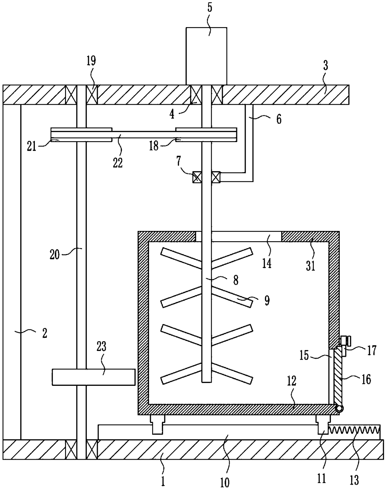
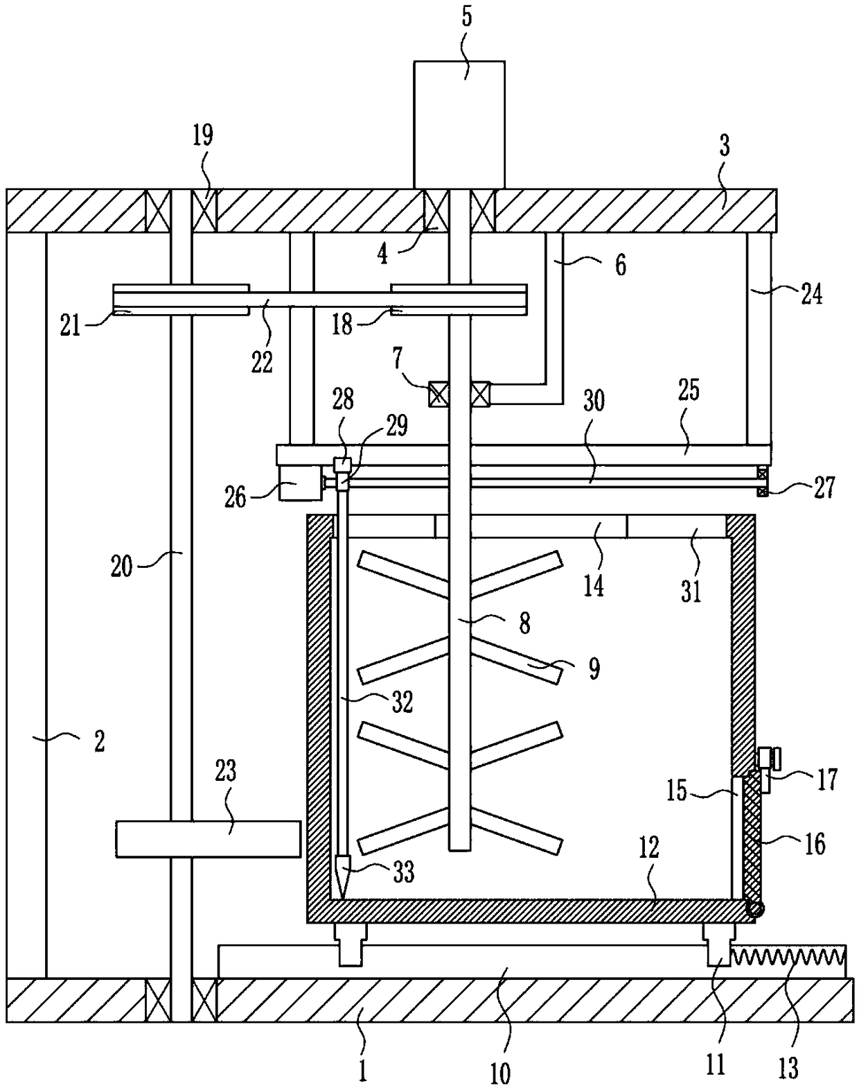
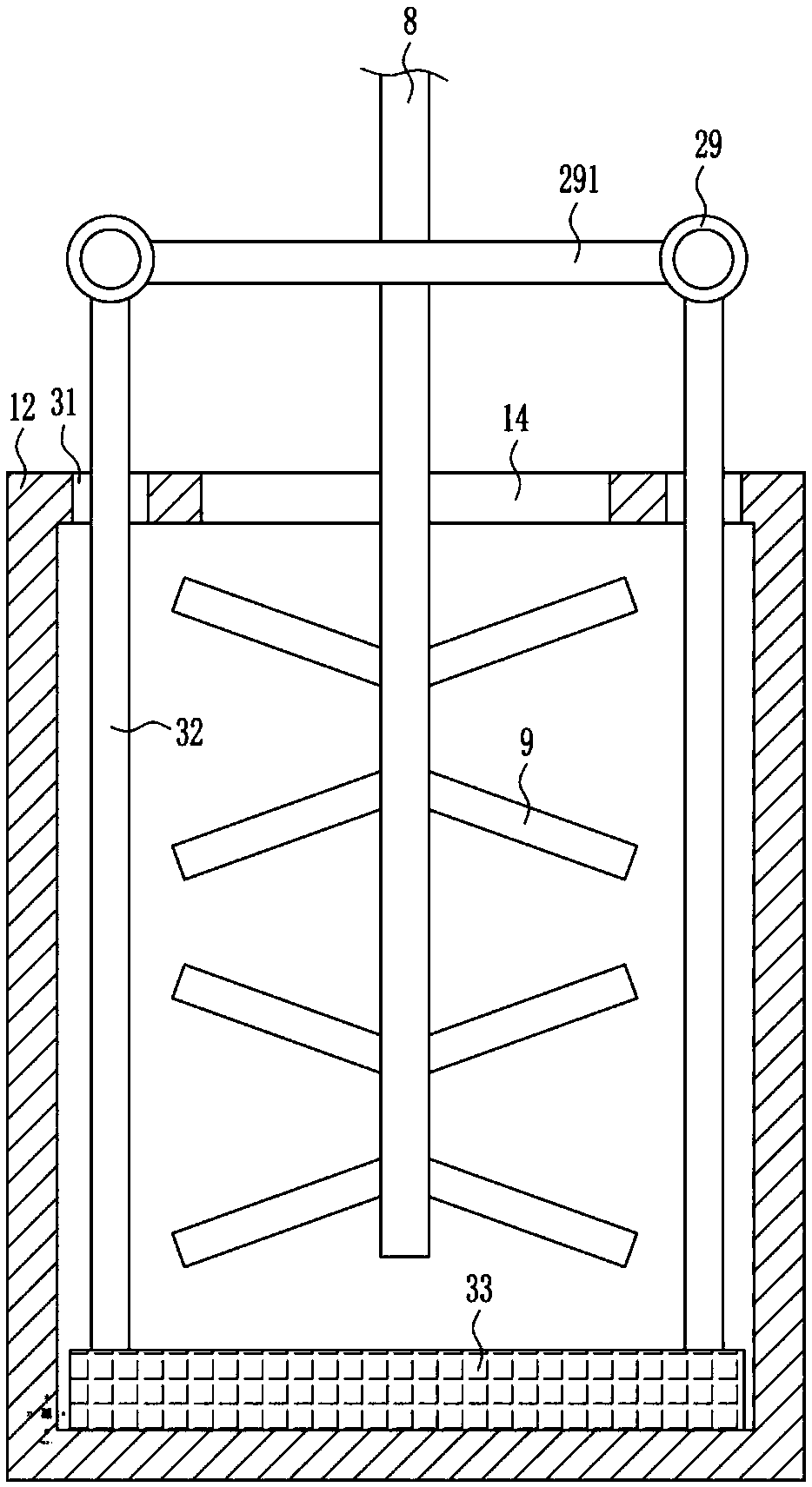
[0022] A water utilization concrete mixing device, such as Figure 1-5As shown, it includes a bottom plate 1, a support plate 2, a top plate 3, a first bearing seat 4, a first motor 5, an L-shaped rod 6, a second bearing seat 7, a first rotating shaft 8, a stirring blade 9, and a first slide rail 10. The first slider 11, the mixing box 12, the first spring 13, the baffle plate 16, the card plate 17, the first pulley 18, the third bearing seat 19, the second rotating shaft 20, the second pulley 21, the flat belt 22 And cam 23, bottom plate 1 top left is equipped with support plate 2, and support plate 2 top is equipped with top plate 3, and top plate 3 right side is embedded with first bearing seat 4, and top plate 3 top right is installed with first motor 5 , the bottom right of the top plate 3 is equipped with an L-shaped rod 6, the left end of the L-shaped rod 6 is equipped with a second bearing seat 7, the first shaft 8 is connected between the bearings in the first bearing...

Embodiment 2

[0024] A water utilization concrete mixing device, such as Figure 1-5 As shown, it includes a bottom plate 1, a support plate 2, a top plate 3, a first bearing seat 4, a first motor 5, an L-shaped rod 6, a second bearing seat 7, a first rotating shaft 8, a stirring blade 9, and a first slide rail 10. The first slider 11, the mixing box 12, the first spring 13, the baffle plate 16, the card plate 17, the first pulley 18, the third bearing seat 19, the second rotating shaft 20, the second pulley 21, the flat belt 22 And cam 23, bottom plate 1 top left is equipped with support plate 2, and support plate 2 top is equipped with top plate 3, and top plate 3 right side is embedded with first bearing seat 4, and top plate 3 top right is installed with first motor 5 , the bottom right of the top plate 3 is equipped with an L-shaped rod 6, the left end of the L-shaped rod 6 is equipped with a second bearing seat 7, the first shaft 8 is connected between the bearings in the first bearin...

Embodiment 3

[0027] A water utilization concrete mixing device, such as Figure 1-5 As shown, it includes a bottom plate 1, a support plate 2, a top plate 3, a first bearing seat 4, a first motor 5, an L-shaped rod 6, a second bearing seat 7, a first rotating shaft 8, a stirring blade 9, and a first slide rail 10. The first slider 11, the mixing box 12, the first spring 13, the baffle plate 16, the card plate 17, the first pulley 18, the third bearing seat 19, the second rotating shaft 20, the second pulley 21, the flat belt 22 And cam 23, bottom plate 1 top left is equipped with support plate 2, and support plate 2 top is equipped with top plate 3, and top plate 3 right side is embedded with first bearing seat 4, and top plate 3 top right is installed with first motor 5 , the bottom right of the top plate 3 is equipped with an L-shaped rod 6, the left end of the L-shaped rod 6 is equipped with a second bearing seat 7, the first shaft 8 is connected between the bearings in the first bearin...


PUM


Abstract

The invention relates to a stirring device, in particular to a concrete stirring device used for hydraulic engineering. According to the concrete stirring device used for hydraulic engineering, the concrete stirring speed is high, and concrete is unlikely to splash when stirred. The concrete stirring device used for hydraulic engineering comprises a bottom plate, a supporting plate, a top plate, afirst bearing seat, a first motor, an L-shaped rod, a second bearing seat, a first rotary shaft and the like. The supporting plate is mounted on the left side of the top of the bottom plate. The topplate is mounted at the top of the supporting plate. The first bearing seat is mounted on the right side of the top plate in an embedded mode. The first motor is mounted on the right side of the top of the top plate. According to the concrete stirring device used for hydraulic engineering, stirring blades are driven by the first motor to stir concrete, a stirring box can be driven by a cam to continuously move leftwards and rightwards, and thus, the concrete stirring efficiency can be improved; and a scraping plate is arranged so that concrete can be easily pushed out through the scraping plate after being stirred, and the effects that the concrete stirring speed is high and the concrete is unlikely to splash when stirred are achieved.

Description

technical field [0001] The invention relates to a stirring device, in particular to a water utilization concrete stirring device. Background technique [0002] Water conservancy projects are projects built to control and allocate natural surface water and groundwater to achieve the purpose of eliminating harm and rejuvenating profits. Also known as water engineering. Water is an indispensable precious resource for human production and life, but its natural state does not fully meet human needs. Only by building water conservancy projects can we control water flow, prevent floods, and regulate and distribute water to meet the needs of people's life and production for water resources. Water conservancy projects need to build different types of hydraulic structures such as dams, dikes, spillways, sluices, water inlets, channels, canals, rafts, and fishways to achieve their goals. [0003] In order to prevent floods from destroying crops, it is necessary to build dams in the ...

Claims


Application Information

Patent Timeline
IPC IPC(8): B28C5/16B28C5/48
CPCB28C5/16B28C5/485
Inventor 蒋孔满安梦琪吴王博
Owner 蒋孔满
Why Eureka
Try Eureka