Supercharge Your Innovation With Domain-Expert AI Agents!

Superspeed elevator car

An elevator car, ultra-high-speed technology, applied in elevators in buildings, non-rotational vibration suppression, transportation and packaging, etc., can solve problems such as inability to prevent mutual influence and transmission, no better technical solutions, and inability to isolate the shaft , to achieve the effect of reducing noise and vibration, easy to implement, and reasonable structural design

Inactive Publication Date: 2018-10-26
浙江巨人集团有限公司
View PDF4 Cites 3 Cited by
  • Summary
  • Abstract
  • Description
  • Claims
  • Application Information

AI Technical Summary

Problems solved by technology

[0002] In recent years, with the vigorous development of super high-rise buildings, the market for ultra-high-speed elevators has become larger and larger, but the market for ultra-high-speed elevators is basically monopolized by foreign companies, and the main factor affecting their comfort comes from the noise and vibration generated during elevator operation , there are professional supporting manufacturers in the market for components that affect their performance, such as machine rooms, guide rails, wire ropes, guide shoes, and control systems. The main component that causes the difference in comfort is the car that is in zero-distance contact with passengers. There has been no better technical solution. Although there is a soundproof car in the prior art, it only isolates the noise outside the car, and cannot isolate the noise and vibration of the shaft during elevator operation from the inside of the car. The noise and vibration of each component cannot prevent mutual influence and transmission

Method used


Image

  • Superspeed elevator car
  • Superspeed elevator car
  • Superspeed elevator car

Examples


Embodiment Construction

[0023] The present invention will be further described in detail below in conjunction with the accompanying drawings, and specific implementation methods will be given.

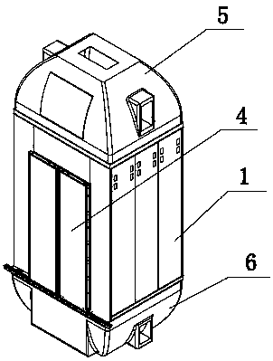
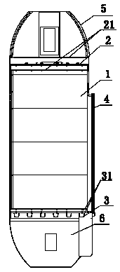
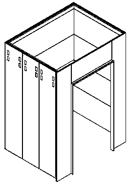
[0024] like Figure 1-6 As shown, the present invention is an ultra-high-speed elevator car, its main purpose is to provide a complete technical solution for reducing the noise and vibration of the elevator car, and the design of each component can be combined and used according to the actual running speed of the elevator for Super high-speed elevator with a speed of 6-18m / s.

[0025] The specific structure includes a sound-proof and shock-absorbing car wall 1, a sound-insulating and shock-absorbing car roof 2, a sound-insulating and shock-absorbing car floor 3, a car door 4, an upper nozzle 5 and a lower nozzle 6; a sound-proof and shock-absorbing car wall 1, which includes a car The car wall base plate 11 of the car, and the adjacent car wall base plates 11 are connected and arranged through a shock absorb...


PUM


Abstract

The invention discloses a superspeed elevator car. The superspeed elevator car comprises sound-insulation damping car walls, a sound-insulation damping car roof, a sound-insulation damping car base, acar door, an upper flow guide cover and a lower flow guide cover. The sound-insulation damping car walls comprises car wall substrates of the elevator car; the adjacent car wall substrates are connected by a damping mechanism; upper damping pads are arranged among the sound-insulation damping car roof, the upper flow guide cover and the sound-insulation damping car walls; lower damping pads are arranged among the sound-insulation damping car base, the lower flow guide cover and the sound-insulation damping car walls; a clamping structure is formed among the car door and three sides of the sound-insulation damping car walls; and wind block hairbrushes are arranged at the lower ends of the car door. Through the arrangement of the damping pads, vibration of parts and noise disturbance are effectively avoided; through the arrangement of the structure of the sound-insulation damping car walls, outer noise and vibration can hardly transmit into the elevator car; and the arrangement of damping strips and damping bolts further reduces the noise and vibration, noise and vibration in an elevator shaft are separated from the inner portion of the elevator car, and noise and vibration of eachpart do not transmit.

Description

technical field [0001] The invention belongs to the technical field of elevator equipment, and in particular relates to an ultra-high-speed elevator car. Background technique [0002] In recent years, with the vigorous development of super high-rise buildings, the market for ultra-high-speed elevators has become larger and larger, but the market for ultra-high-speed elevators is basically monopolized by foreign companies, and the main factor affecting their comfort comes from the noise and vibration generated during elevator operation , there are professional supporting manufacturers in the market for components that affect their performance, such as machine rooms, guide rails, wire ropes, guide shoes, and control systems. The main component that causes the difference in comfort is the car that is in zero-distance contact with passengers. There has been no better technical solution. Although there is a soundproof car in the prior art, it only isolates the noise outside the c...

Claims


Application Information

Patent Timeline
IPC IPC(8): B66B11/02F16F15/02
CPCB66B11/0226F16F15/02
Inventor 刘光来莫建芳赵书红顾惠江陈伟汤晨梁灵辉曹向阳余斌施振强王屹
Owner 浙江巨人集团有限公司
Features
  • R&D
  • Intellectual Property
  • Life Sciences
  • Materials
  • Tech Scout
  • Unparalleled Data Quality
  • Higher Quality Content
  • 60% Fewer Hallucinations
Learn More