
Waste water valve

A waste water valve and valve body technology, applied in the direction of sliding valves, valve details, valve devices, etc., can solve the problems of increasing the processing cost of enterprises, destroying the ecological environment, and occupying a large amount of stirring devices, so as to reduce the cost of waste water treatment and facilitate use , The effect of simple device structure

Inactive Publication Date: 2018-10-26
PUJIANG ZHIYIN TECH CO LTD
View PDF0 Cites 2 Cited by
  • Summary
  • Abstract
  • Description
  • Claims
  • Application Information

AI Technical Summary

Problems solved by technology

[0002] In industrial production, it is inevitable to produce a lot of waste water. In the past, the discharge everywhere has caused the destruction of the ecological environment. With the continuous improvement of people's environmental protection awareness, industrial waste water needs special treatment before it can be discharged. Traditional The treatment method of industrial wastewater is to discharge the wastewater into the waste water pool, and then put the treatment agent into the waste water pool. In order to avoid uniform mixing, the waste water pool is generally equipped with a stirring device. Therefore, this will increase the treatment cost of the enterprise. , and the stirring device will take up a lot of space

Method used


Image

  • Waste water valve
  • Waste water valve

Examples


Embodiment Construction

[0018] All features disclosed in this specification, or steps in all methods or processes disclosed, may be combined in any manner, except for mutually exclusive features and / or steps.

[0019] Any feature disclosed in this specification, unless specifically stated, can be replaced by other alternative features that are equivalent or have similar purposes. That is, unless expressly stated otherwise, each feature is one example only of a series of equivalent or similar features.

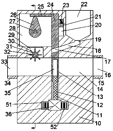
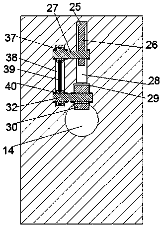
[0020] Such as Figure 1 to Figure 2 As shown, a waste water valve of the device of the present invention includes a valve body 10, a left and right water passage 14 is arranged in the valve body 10, a water inlet pipe 34 is fixedly installed on the left end surface of the valve body 10, and the water inlet pipe 34 is provided with a water inlet tank 33 communicating with the water tank 14, and the right end surface of the valve body 10 is fixedly equipped with a water outlet pipe 15, and the water o...


PUM


Abstract

The invention discloses a waste water valve. The waste water valve comprises a valve body. The valve body is internally provided with a left-right interlinked water passing groove. The left end face of the valve body is fixedly provided with a water inlet pipe. The water inlet pipe is internally provided with a water inlet groove communicating with the water passing groove. The right end face of the valve body is fixedly provided with a water outlet pipe. The water outlet pipe is internally provided with a water outlet groove communicating with the water passing groove. The bottom wall of thewater passing groove is provided with a first sliding groove in a communication manner, and the first sliding groove extends downwards. The first sliding groove is internally provided with a valve plate in a sliding manner. The valve plate is internally provided with an internal thread groove with a downward opening. The internal thread groove is internally provided with a threaded rod in a threadfit manner. The lower end of the threaded rod is in power connection with a drive motor which is fixedly installed in the bottom wall of the first sliding groove. The top wall of the water passing groove is internally provided with a second sliding groove communicating with the water passing groove. The second sliding groove is internally provided with an extensible and retractable plate in a sliding manner. The extensible and retractable plate is internally provided with a first oblique groove. The right side of the second sliding groove is provided with a material cavity with an upward opening.

Description

technical field [0001] The invention relates to the field of valves, in particular to a waste water valve. Background technique [0002] In industrial production, it is inevitable to produce a lot of waste water. In the past, the discharge everywhere has caused the destruction of the ecological environment. With the continuous improvement of people's environmental protection awareness, industrial waste water needs special treatment before it can be discharged. Traditional The treatment method of industrial wastewater is to discharge the wastewater into the waste water pool, and then put the treatment agent into the waste water pool. In order to avoid uniform mixing, the waste water pool is generally equipped with a stirring device. Therefore, this will increase the treatment cost of the enterprise. , and the stirring device also takes up a lot of space. Contents of the invention [0003] Aiming at the deficiencies of the above technologies, the present invention propose...

Claims


Application Information

Patent Timeline
Patent Type & Authority Applications(China)
IPC IPC(8): F16K3/02F16K3/314F16K31/04F16K31/50F16K49/00F16K3/30C02F1/00
CPCF16K3/02C02F1/00C02F2201/005F16K3/30F16K3/314F16K31/047F16K31/50F16K49/00
Inventor 朱林祥
Owner PUJIANG ZHIYIN TECH CO LTD
Learn More