Embedding method of fiber-shaped sample for axial ultrathin slice

An ultra-thin section, fibrous technology, applied in the field of ultra-thin section, can solve problems such as accurate positioning, achieve the effect of improving the success rate, improving the efficiency of later trimming and the success rate of slicing

Inactive Publication Date: 2018-10-26
EAST CHINA UNIV OF SCI & TECH
View PDF5 Cites 9 Cited by
  • Summary
  • Abstract
  • Description
  • Claims
  • Application Information

AI Technical Summary

Problems solved by technology

This embedding method overcomes the problem that the fiber cannot be accurately positioned when the ultra-thin section is trimmed after the fiber is embedded with epoxy resin in the early stage, and greatly improves the efficiency of later trimming and the success rate of slicing.

Method used


Image

  • Embedding method of fiber-shaped sample for axial ultrathin slice
  • Embedding method of fiber-shaped sample for axial ultrathin slice
  • Embedding method of fiber-shaped sample for axial ultrathin slice

Examples


Embodiment 1

[0052] This embodiment involves using the embedding method of the present application to embed colorless and transparent PET nanocomposite fibers, and then perform ultrathin sectioning and high-resolution TEM photography.

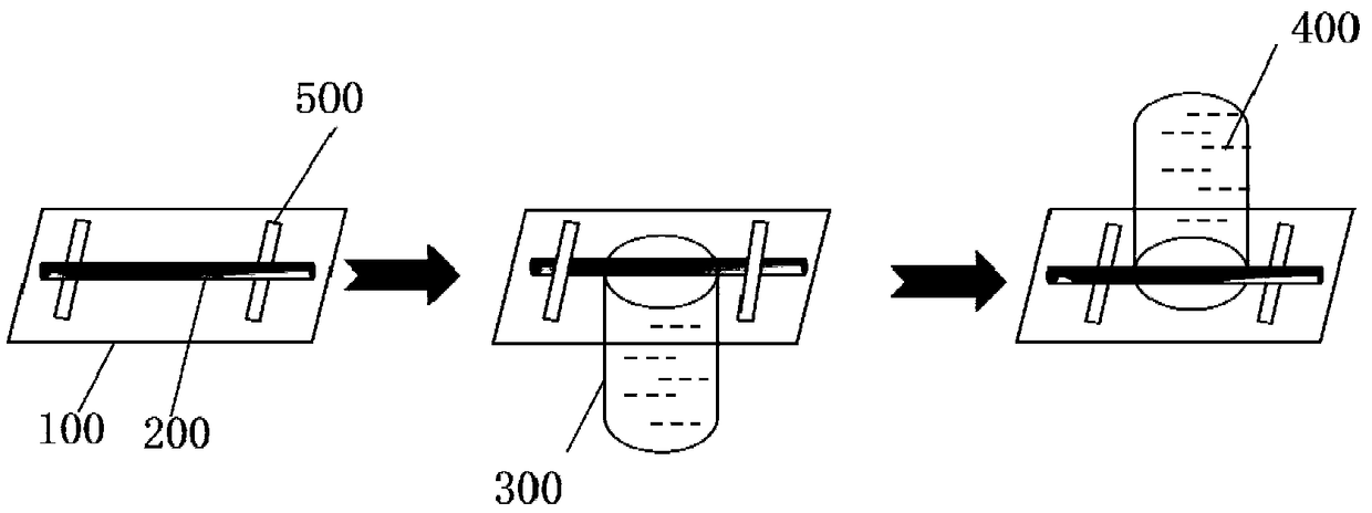
[0053] The embedding method of the fibrous sample that is used for the axial ultrathin section of the present invention comprises the following steps: first, on a piece of clean glass slide, several colorless and transparent PET nanocomposite fibers (diameter is 5mm) ~15 microns) fixed, the PET nano-composite fiber is straightened as far as possible to be linear; then the embedding agent epoxy resin Epon812 is filled in the embedding mold opening plastic capsule until the liquid level of the liquid embedding agent is in line with the opening The upper surface of the container is flush, and air bubbles should be avoided in the sample area during this process; finally, the glass slide fixed with the PET nanocomposite fiber is buckled on the top of the open pla...

Embodiment 2

[0056] This embodiment involves embedding hair with the embedding method of the present application, and then performing ultrathin sectioning and high-resolution TEM photography.

[0057] The embedding method of the fibrous sample that is used for axial ultrathin section of the present invention comprises the following steps: at first, hair (diameter 80~90 microns) is fixed with double-sided tape on a piece of clean slide glass, and hair is pulled as far as possible. Straight without bending, 3 to 4 hairs can be arranged in parallel for fixation; then fill the embedding agent epoxy resin Epon812 in the embedding mold opening plastic capsule until the liquid level of the liquid embedding agent meets the open container During this process, air bubbles should be avoided as much as possible in the sample area; finally, the glass slide with the hair fixed is buckled on the top of the open plastic capsule, so that the surface of the glass slide with the hair fixed faces the open plas...


PUM

PropertyMeasurementUnit
diameteraaaaaaaaaa

Abstract

The invention discloses an embedding method of a fiber-shaped sample for an axial ultrathin slice. The embedding method comprises the following steps: fixing the fiber-shaped sample on a substrate toenable the fiber-shaped sample to be linear on the substrate; adding a liquid embedding agent into an open container; then covering the substrate fixed with the fiber-shaped sample on the top of the open container and enabling the surface fixed with the fiber-shaped sample of the substrate to be arranged toward the open container; fixing the substrate and the open container; then integrally overturning the substrate and the open container; reversely buckling the open container on the surface fixed with the fiber-shaped sample of the substrate; curing the liquid embedding agent to form an embedding block; separating the open container and the substrate and enabling the fiber-shaped sample to be located at a position of the topmost end of the embedding block, so as to obtain an embedded fiber-shaped sample for the axial ultrathin slice. The method disclosed by the invention can be used for accurately determining the position of the sample and remarkably improving the later-period block trimming efficiency and the success rate of slicing.

Description

technical field [0001] The present application relates to the technical field of ultrathin sections, in particular, to an embedding method for fibrous samples used in axial ultrathin sections. Background technique [0002] In traditional methods for axial ultrathin sectioning of fibrous samples including fibers, the fibrous sample is usually placed in an embedding plate, then poured into a resin for embedding, and the resulting embedding block is subjected to ultrathin sectioning deal with. However, this method is usually difficult to ensure that the fibrous sample is directly exposed to the end of the embedding block to be cut. In the subsequent trimming process, it is generally difficult to accurately locate the embedded fibrous material under a microscope, which may cause miscutting, which in turn leads to the failure of the fibrous sample to be characterized when observing the section with a transmission electron microscope (TEM). This will greatly waste the time and e...

Claims


Application Information

Patent Timeline
Patent Type & Authority Applications(China)
IPC IPC(8): G01N1/36G01N1/28
CPCG01N1/286G01N1/36G01N2001/2873G01N2001/364G01N2001/366
Inventor 李金霞周丽绘唐静
Owner EAST CHINA UNIV OF SCI & TECH
Why Eureka
Try Eureka