
Collimation backlight module and display device

A technology of backlight modules and gratings, applied in light guides, optics, optical components, etc., can solve problems such as very large demand, color filter transmittance of only 27%, and bulky structure

Active Publication Date: 2018-10-26
BOE TECH GRP CO LTD
View PDF5 Cites 22 Cited by
  • Summary
  • Abstract
  • Description
  • Claims
  • Application Information

AI Technical Summary

Problems solved by technology

Color filters are the key components of LCD. At present, most of the color filters basically need to be purchased from abroad, the cost is high, and the transmittance of the color filters is only 27%, which is the only LCD with a light energy utilization rate of less than 5%. main reason
[0003] In addition, most of the near-eye display solutions such as AR / VR on the market are based on collimated backlight design, but the current collimated backlight solutions are all focused on monochromatic collimation or bulky lens collimation solutions, so , the demand for thin and simple collimated backlight structure and technology is very large. If the color thin and light collimated backlight can be realized, it will promote the express development of AR / VR industry
However, in the current collimated backlight, only a single color of light can be extracted through collimation, so it is essentially a monochrome display solution. Therefore, it is necessary to propose a color display solution that is conducive to industrialization

Method used


Image

  • Collimation backlight module and display device
  • Collimation backlight module and display device
  • Collimation backlight module and display device

Examples


Embodiment Construction

[0060] In order to make the purpose, technical solutions and advantages of the embodiments of the present invention more clear, the following will clearly and completely describe the technical solutions of the embodiments of the present invention in conjunction with the drawings of the embodiments of the present invention. Apparently, the described embodiments are some, not all, embodiments of the present invention. All other embodiments obtained by those skilled in the art based on the described embodiments of the present invention belong to the protection scope of the present invention.

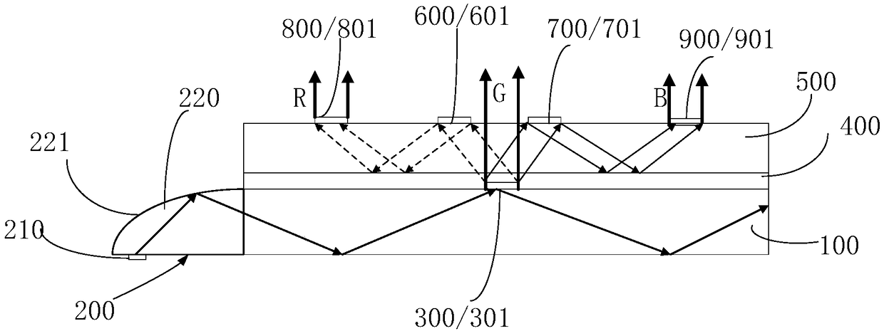
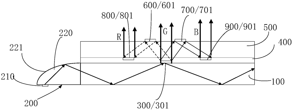
[0061] In view of the fact that the collimated backlight module in the prior art can only provide monochromatic collimated light, if a color display is realized, a structure such as a color filter needs to be installed, which is not conducive to the thinning of the structure, and the low transmittance of the color filter causes light In order to solve problems such as low energy utilization...


PUM


Abstract

The invention provides a collimation backlight module and a display device. The collimation backlight module comprises a first light guide plate, a collimation light source, a first collimation lighttaking part, a first flat layer, a second light guide plate, a first diffraction modulation part, a second diffraction modulation part, a second collimation light taking part and a third collimation light taking part and is characterized in that the collimation light source couples collimation light into the first light plate to perform total reflection transmission; the first collimation light taking part takes out first-color light in the collimation light in the first light guide plate in a way that the first color light is vertical to a first light-emitting face and in a collimation manner, takes out the second-color light in the collimation light in the first light guide plate at first inclination angle and in a collimation manner and takes out the third-color light in the collimationlight in the first light guide plate at second inclination angle and in a collimation manner; the first flat layer covers the light-emitting face of the first light guide plate; the second light guide plate is arranged on the first flat layer; the first diffraction modulation part couples the second-color light into the second light guide plate inn a diffraction modulation manner to perform totalreflection transmission; the second diffraction modulation part couples the third-color light into the second light guide plate in a diffraction modulation manner to perform total reflection transmission; the second collimation light taking part vertically takes out the second-color light in a collimation manner; the third collimation light taking part vertically takes out the third-color light in a collimation manner. The collimation backlight module can provide three-color collimation backlight to achieve colored display.

Description

technical field [0001] The invention relates to the field of display technology, in particular to a collimation backlight module and a display device. Background technique [0002] In a traditional liquid crystal display (Liquid Crystal Display, LCD), the backlight module provides the illumination source, and the light wave is polarized through the polarizer (polarizer), enters the liquid crystal panel after being modulated, and then passes through the analyzer (polarizer) and Color filters, presenting colorful images. Color filters are the key components of LCD. At present, most of the color filters basically need to be purchased from abroad, the cost is high, and the transmittance of the color filters is only 27%, which is the only LCD with a light energy utilization rate of less than 5%. main reason. [0003] In addition, most of the near-eye display solutions such as AR / VR on the market are based on collimated backlight design, but the current collimated backlight solu...

Claims


Application Information

Patent Timeline
IPC IPC(8): G02F1/13357G02B6/00G02F1/1335G02F1/1343
CPCG02B6/005G02B6/0076G02F1/133512G02F1/133606G02F1/133621G02F1/1343
Inventor 孟宪东谭纪风孟宪芹王维陈小川高健王方舟
Owner BOE TECH GRP CO LTD
Learn More