
Thermoelectric conversion module

A technology of thermoelectric conversion and thermal conductivity, which is applied in the direction of thermoelectric device parts, manufacturing/processing of thermoelectric devices, thermoelectric device node lead-out materials, etc., can solve problems such as damage and stripping components, and achieve the effect of preventing damage

Active Publication Date: 2018-10-26
MITSUBISHI MATERIALS CORP
View PDF12 Cites 0 Cited by
  • Summary
  • Abstract
  • Description
  • Claims
  • Application Information

AI Technical Summary

Problems solved by technology

Therefore, in a structure in which one side and the other side of the n-type thermoelectric conversion element and the p-type thermoelectric conversion element are joined to a single insulating plate as in the past, due to the difference in the thermal expansion coefficients of the n-type thermoelectric conversion element and the p-type thermoelectric conversion element, Different, there is a possibility that one of the thermoelectric conversion elements is peeled off from the insulating plate or the element is damaged

Method used


Image

  • Thermoelectric conversion module
  • Thermoelectric conversion module
  • Thermoelectric conversion module

Examples


Embodiment Construction

[0037] Hereinafter, the thermoelectric conversion module of the present invention will be described with reference to the drawings. In addition, each embodiment shown below is an embodiment concretely demonstrated for better understanding of the gist of invention, Unless otherwise specified, this invention is not limited. In addition, in the drawings used in the following description, in order to facilitate the understanding of the characteristics of the present invention, the main parts may be shown enlarged for convenience of description, and the dimensional ratio of each component may not necessarily be the same as the actual one.

[0038] (Thermoelectric conversion module: first embodiment)

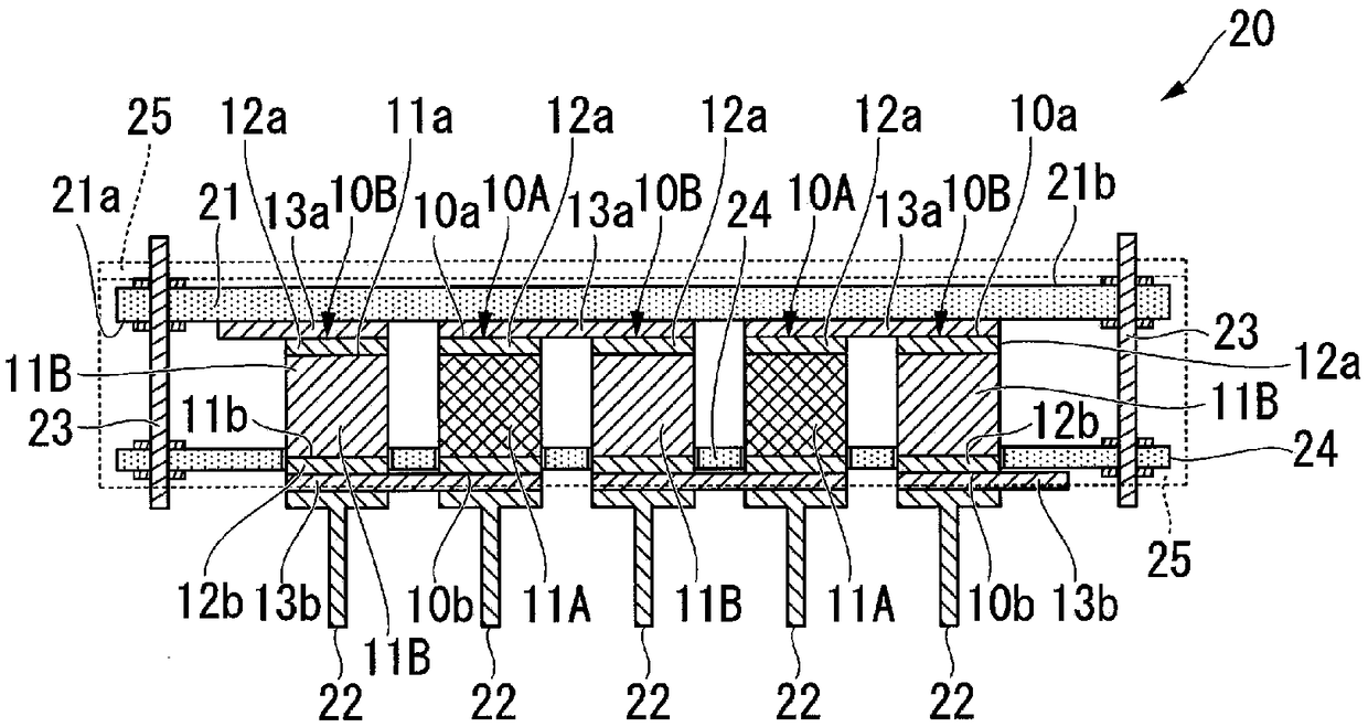
[0039] figure 1 It is a cross-sectional view of the thermoelectric conversion module according to the first embodiment viewed from the side.

[0040] The thermoelectric conversion module 20 of the first embodiment is a π (Pi) type thermoelectric conversion module in which different ...


PUM

PropertyMeasurementUnit
Thermal conductivityaaaaaaaaaa

Abstract

A thermoelectric conversion module according to the present invention is characterized in that: an n-type thermoelectric conversion element and a p-type thermoelectric conversion element are configured from materials having mutually different thermal expansion coefficients; one surface side of the n-type thermoelectric conversion element and one surface side of the p-type thermoelectric conversionelement are aligned and joined to one surface side of a shared insulating substrate; and a heat conducting member is independently and individually formed on the other surface side of the n-type thermoelectric conversion element and on the other surface side of the p-type thermoelectric conversion element.

Description

technical field [0001] The invention relates to a thermoelectric conversion module formed by electrically connecting a plurality of thermoelectric conversion elements. [0002] This application claims priority based on the patent application No. 2016-060866 filed in Japan on March 24, 2016 and the patent application No. 2017-033837 filed in Japan on February 24, 2017, and the contents thereof are incorporated herein. Background technique [0003] The thermoelectric conversion element is an electronic element capable of mutual conversion of heat and electricity called Seebeck effect or Peltier effect. The Seebeck effect is an effect of converting thermal energy into electrical energy, and is a phenomenon in which an electromotive force is generated when a temperature difference occurs between both ends of a thermoelectric conversion material. This electromotive force is determined by the characteristics of the thermoelectric conversion material. In recent years, development...

Claims


Application Information

Patent Timeline
IPC IPC(8): H01L35/30F25B21/02H02N11/00
CPCF25B21/02H10N10/817H10N10/17H10N10/13H10N10/85H10N10/80H10N10/01H10N10/855
Inventor 中田嘉信
Owner MITSUBISHI MATERIALS CORP
Learn More