a mixing tank

A technology of agitating tank and agitating shaft, which is used in mixer accessories, mixers with rotating mixing devices, mixers, etc., can solve the problems of limited improvement of material flow conditions, and achieve improved mixing efficiency, improved mixing effect, and increased The effect of velocity gradients

Active Publication Date: 2020-12-15
INST OF PROCESS ENG CHINESE ACAD OF SCI
View PDF25 Cites 0 Cited by
  • Summary
  • Abstract
  • Description
  • Claims
  • Application Information

AI Technical Summary

Problems solved by technology

[0005] The purpose of the present invention is to propose a stirring tank to solve the problem that the existing baffles have limited effect on improving the material flow condition, so as to further improve the stirring efficiency of the stirring tank

Method used


Image

  • a mixing tank
  • a mixing tank
  • a mixing tank

Examples


Embodiment 1

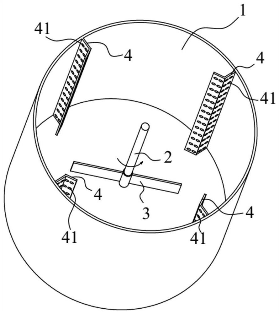
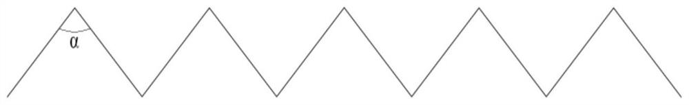
[0043] Such as figure 1 As shown, the tank body 1 diameter of the stirring tank in the present embodiment is 282mm, the height of the tank body 1 is 300mm, the paddle 3 is two straight blade paddles, the paddle diameter is 140mm, the paddle height is 28mm, and the distance between the paddle 3 The height of the bottom of the tank body 1 is 93 mm. Four baffle plates 4 are attached and installed with the inner wall of the tank body 1, and the top view of the baffle plate 4 is a broken line shape (such as figure 2 shown in ), the angle α between two adjacent broken lines is 90°, the length of the baffle plate 4 along the radial direction of the tank body 1 is 28mm, and the lengthwise dimension of the baffle plate 4 is 300mm. The diameter of the through-flow holes 41 is 5 mm, and the center-to-center distance between two adjacent through-flow holes 41 is 10 mm. In this embodiment, the stirring medium in the stirring tank is water, the height of the liquid level is 282 mm, the t...

Embodiment 2

[0045] The difference from the first embodiment is that the diameter of the through-flow hole 41 is 50 mm.

Embodiment 3

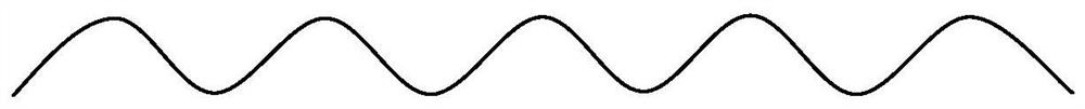
[0047] The difference from Embodiment 1 is that, as image 3 As shown, the shape of the cross section of the baffle plate 4 is a wavy shape formed by arcs.


PUM


Abstract

The invention discloses a stirring tank and relates to the technical field of stirring devices. The stirring tank includes a tank body, a stirring shaft, paddles and baffles, the tank body is used to hold materials to be stirred; the axis of the stirring shaft coincides with the axis of the tank body; the paddles are arranged on the stirring shaft; the baffles are arranged on Inside the tank and located on the outer periphery of the stirring shaft, the baffle plate is provided with flow holes, and the cross section of the baffle plate is wavy. In the stirring tank of the present invention, during the stirring process of the paddle, the fluid passes through the through-flow hole to form many high-speed jets. Since the cross section of the baffle is wavy, the high-speed jets will collide with each other after passing through the baffle to form a collision flow. Therefore, the velocity gradient of the fluid in the baffle area in the stirring tank is further increased, the flow condition in the flow stagnation area behind the baffle is improved, the mixing effect of the fluid is improved, and the stirring efficiency of the stirring tank is improved.

Description

technical field [0001] The invention relates to the technical field of stirring devices, in particular to a stirring tank. Background technique [0002] Stirring tank is one of the important equipment for material mixing and reaction in chemical production process. The stirring tank generally mainly includes the tank body and the stirring shaft inside the tank body, paddles and baffles, the stirring shaft is set on the central axis of the tank body, the paddles are fixed on the stirring shaft, and the baffles are fixed on the inner wall of the tank body superior. In the stirred tank, the paddle rotates to generate discharge flow, which forms a complex flow field due to the action of the inner wall of the tank and the baffle, and the flow pattern, flow velocity and flow direction of the discharge flow are all due to the interaction between the paddle and the baffle. And change. Therefore, the configuration and assembly method of the paddle and baffle are important factors ...

Claims


Application Information

Patent Timeline
Patent Type & Authority Patents(China)
IPC IPC(8): B01F7/18B01F15/00
CPCB01F27/1125B01F27/808B01F27/902B01F35/5312B01F27/86B01F27/191B01F27/9021B01F27/112
Inventor 杨超张庆华毛在砂李向阳冯鑫
Owner INST OF PROCESS ENG CHINESE ACAD OF SCI
Why Eureka
Try Eureka