
Stamping device for buckle plate of hardware lock body with adjustable rack

A punching device and adjustable technology, applied in the direction of peeling device, feeding device, storage device, etc., can solve the problems of affecting the punching effect, unsafe, incomplete punching of the gusset plate of the hardware lock body, etc., to maintain the plate body. The effect of the stamping effect

Inactive Publication Date: 2018-10-30
FOSHAN DAPUGUANG ELECTROMECHANICAL TECH CO LTD
View PDF6 Cites 4 Cited by
  • Summary
  • Abstract
  • Description
  • Claims
  • Application Information

AI Technical Summary

Problems solved by technology

[0002] When the existing metal lock body gusset is installed and stamped, the height of the lower die cannot be adjusted, and the downward stroke of the upper die is the same. When punching holes, the thick metal lock body gusset will not be punched completely, and the thinner metal lock body gusset will adhere to the upper mold after punching, which will affect the punching effect, and generally after punching, the waste It is in the mold and needs to be removed manually, which is very troublesome and unsafe

Method used


Image

  • Stamping device for buckle plate of hardware lock body with adjustable rack
  • Stamping device for buckle plate of hardware lock body with adjustable rack

Examples


Embodiment

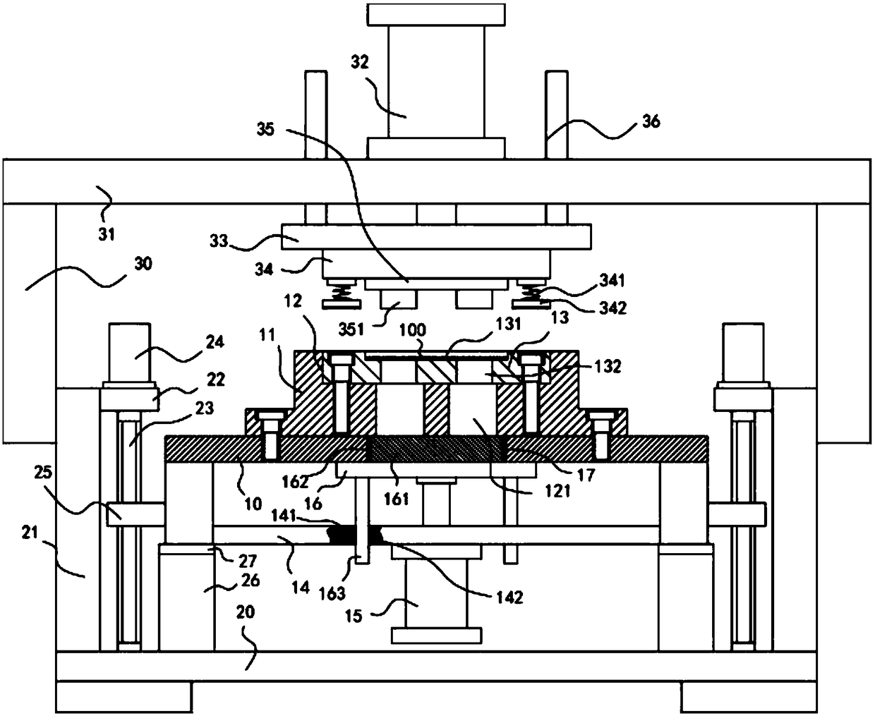
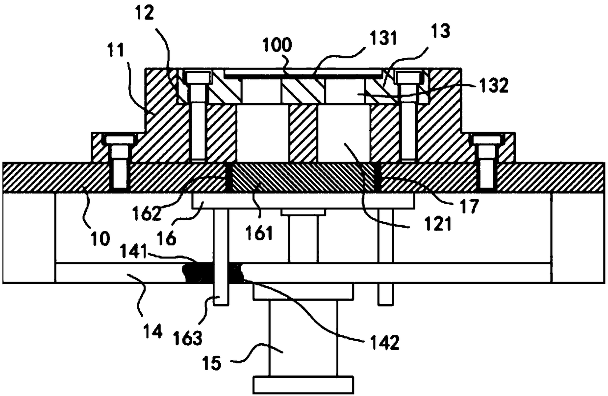
[0019] Example: see Figure 1 to Figure 2 As shown, a frame adjustable metal lock body gusset stamping device includes a frame 10 and a main base plate 20, the left and right sides of the top surface of the main base plate 20 are fixed with vertical main boards 21, two vertical main boards The upper part of the outer wall of 21 is fixed with upper support block 30, and main top plate 31 is fixed on the top surface of two upper support blocks 30, and the middle part top surface of main top plate 31 is fixed with main stamping oil cylinder 32, and the push of main stamping oil cylinder 32 The rod passes through the main top plate 31 and is fixed with a lifting connecting plate 33. The bottom surface of the lifting connecting plate 33 is fixed with an upper mold mounting block 34, and the bottom surface of the upper mold mounting block 34 is fixed with an upper mold 35. The bottom surface of the upper mold 35 is formed with two Stamping block 351;

[0020] The upper part of the ...


PUM


Abstract

The invention discloses a stamping device for a buckle plate of a hardware lock body with an adjustable rack. The device comprises the rack and a main bottom plate, wherein vertical main plates are fixed to the left and right sides of the top surface of the main bottom plate; upper supporting blocks are fixed to the upper parts of the outer side walls of the two vertical main plates; a main top plate is fixed to the top surfaces of the two upper supporting blocks; a main stamping oil cylinder is fixed to the top surface in the middle of the main top plate; a push rod of the main stamping oil cylinder penetrates the main top plate and a lifting connecting plate is fixed to the push rod; an upper mold mounting block is fixed to the bottom surface of the lifting connecting plate; an upper mold is fixed to the bottom surface of the upper mold mounting block; and two stamping blocks are formed on the bottom surface of the upper mold; connecting plates are fixed to the upper parts of opposite walls of the two vertical main plates. The height position of the lower mold can be adjusted precisely when plate bodies of different thicknesses are stamped, so that the stamping depth of the stamping block of the lower mold is matched that of the upper mold, and the plate body stamping effect is kept. Moreover, stamping waste can be discharged automatically to discharging through holes, and can fall automatically as a positioning block falls.

Description

Technical field: [0001] The invention relates to the technical field of hardware processing equipment, in particular to a stamping device for a frame-adjustable hardware lock body gusset plate. Background technique: [0002] When the existing metal lock body gusset is installed and stamped, the height of the lower die cannot be adjusted, and the downward stroke of the upper die is the same. When punching holes, the thick metal lock body gusset will not be punched completely, and the thinner metal lock body gusset will adhere to the upper mold after punching, which will affect the punching effect, and generally after punching, the waste It is in the mold and needs to be removed manually, which is very troublesome and unsafe. Invention content: [0003] The purpose of the present invention is to address the deficiencies of the prior art, and to provide a frame-adjustable metal lock body gusset stamping device, which can accurately adjust the height and position of the lower...

Claims


Application Information

Patent Timeline
Patent Type & Authority Applications(China)
IPC IPC(8): B21D22/02B21D45/00B21D43/20B21D53/38
CPCB21D22/02B21D43/20B21D45/00B21D53/38
Inventor 张东莲
Owner FOSHAN DAPUGUANG ELECTROMECHANICAL TECH CO LTD
Learn More