Processing method of bow-shaped cross arm

A processing method and technology of cross arm, applied in the field of electric power, can solve problems such as low stamping efficiency, and achieve the effects of improving production efficiency, wide application range and good stability

Active Publication Date: 2022-05-27
维克托电力设备有限公司
View PDF7 Cites 0 Cited by
  • Summary
  • Abstract
  • Description
  • Claims
  • Application Information

AI Technical Summary

Problems solved by technology

[0005] In view of the deficiencies in the prior art, the purpose of the present invention is to provide a bow-shaped cross-arm processing method, which solves the problem that the current stamping equipment on the market can only stamp one position on the workpiece at a time, and the stamping efficiency is low. Greatly improved the efficiency of bow-shaped cross-arm production and molding

Method used


Image

  • Processing method of bow-shaped cross arm
  • Processing method of bow-shaped cross arm
  • Processing method of bow-shaped cross arm

Examples


Embodiment 1

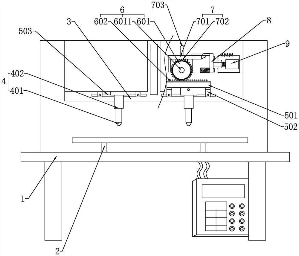
[0069] This embodiment discloses a processing method for a bow-shaped cross-arm, including stamping equipment and workpieces. The stamping equipment has two sets of stamping assemblies 4, and the workpieces are elongated forgings. The following steps are also included:

[0070] S1. Equipment debugging: debug various data of the stamping equipment, and reset the stamping equipment;

[0071] S2. Positioning: Fix the workpiece on the stamping equipment, so that the parts on the workpiece that need to be stamped are opposite to the positions of the two sets of stamping components 4;

[0072] S3. Stamping: Start the stamping equipment and control two sets of stamping components 4 to stamp the workpiece at the same time;

[0073] S4. Shutdown: take off the stamped workpiece and close the stamping equipment.

[0074] see figure 1 , in the present embodiment, the stamping equipment includes: frame 1, piece placing table 2, fixed plate 3, two groups of level adjustment components, wh...

Embodiment 2

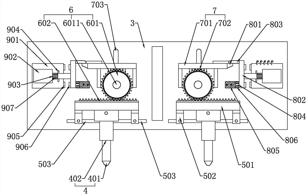
[0084] see Figure 1-Figure 4 , in this embodiment, in addition to including the characteristic structures of the foregoing embodiments, a structure of the horizontal adjustment assembly is further disclosed. The translation seat 501 or the sliding seat 502 moves horizontally; the locking assembly 7 is used to lock the horizontal driving assembly 6 when the stamping assembly 4 does not need to adjust the position; wherein, when the horizontal driving assembly 6 is locked, the sliding seat 502 cannot be relatively fixed. 3 swipe.

[0085] The lifting assembly 402 is connected with the bottom surface of the translation seat 501, one translation seat 501 corresponds to two sliding seats 502, and the two sliding seats 502 are respectively arranged on both sides of the bottom surface of the translation seat 501, the sliding seats 502 are Z-shaped, and the upper end of the sliding seat 502 is in line with the translation The bottom surface of seat 501 is connected, and the surface ...

Embodiment 3

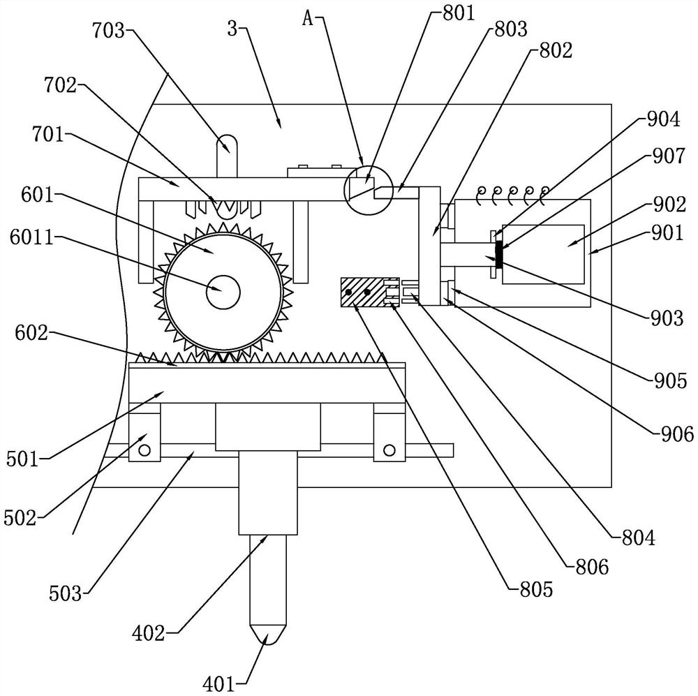
[0093] In this embodiment, in addition to including the characteristic structures of the foregoing embodiments, a structure of the locking component 8 is further disclosed. The specific locking component 8 includes: a limiting block 801, a locking frame 802, a positioning block 805, The electromagnetic drive assembly 9, the specific limit block 801 is fixed on the free end of the locking frame 701 by fasteners; the first end of the clip frame 802 is provided with a clip block 803, and the second end of the clip frame 802 is provided with a positioning insertion rod 804; the positioning block 805 is arranged on the fixed plate 3 and at a position opposite to the second end of the card position frame 802, and the positioning block 805 is provided with a positioning slot 806 on the side surface close to the card position frame 802, and the positioning insertion rod 804 can be snapped into Locate slot 806.

[0094]In the above structure, the position of the positioning block 805 i...


PUM


Abstract

The invention relates to a machining method for a bow-shaped cross arm, stamping equipment and a workpiece are included, the stamping equipment is provided with two sets of stamping assemblies, in the stamping process, the two sets of stamping equipment can stamp two positions needing to be machined on the workpiece at the same time, and for the workpiece with more than two positions to be stamped, the stamping efficiency is greatly improved. The number of times that workpieces need to be clamped is reduced, the production efficiency of the bow-shaped cross arm is improved, in addition, the distance between the two sets of stamping assemblies can be adjusted, the stamping equipment can machine bow-shaped cross arms of more specifications, the application range is wide, the bent portion of the bow-shaped cross arm formed through the machining method does not have gaps, stability is better, and the production efficiency of the bow-shaped cross arm is improved. And in a long-term use process, the wire cannot be damaged due to outdoor strong wind or strong shaking of the wire.

Description

technical field [0001] The invention relates to the field of electric power technology, in particular to a processing method for a bow-shaped cross-arm. Background technique [0002] The cross arm is an important part of the pole tower. Its function is to install insulators and fittings, to support the wires and lightning conductors, and to keep them at a certain safe distance according to the regulations. The function of the cross arm is to fix the top of the pole horizontally. Angle iron with porcelain vases on it is used to support overhead wires. The cross-arm is divided into iron cross-arm, porcelain cross-arm, synthetic insulated cross-arm, etc. [0003] The bow-shaped cross-arms that were widely used before were all formed by electric welding after bending, and fixed on the utility poles through the cooperation of bolts and nuts. When shaken strongly, the bending part is easily damaged, which affects the normal operation of the transmission line; based on these probl...

Claims


Application Information

Patent Timeline
Patent Type & Authority Applications(China)
IPC IPC(8): B21D43/00B21D37/10B21D22/02
CPCB21D43/003B21D37/10B21D22/02
Inventor 郑文科
Owner 维克托电力设备有限公司
Why Eureka
Try Eureka