
Numerical control lathe multi-cutter-position device

A CNC lathe, multi-tool technology, applied in the direction of tool holders, etc., can solve the problems of not making full use of the CNC system, affecting the efficiency and precision of processing, and increasing the labor intensity of workers, so as to achieve simple structure, improve efficiency and processing accuracy, low cost effect

Active Publication Date: 2015-02-25
河南华中星科技电子有限公司
View PDF11 Cites 8 Cited by
  • Summary
  • Abstract
  • Description
  • Claims
  • Application Information

AI Technical Summary

Problems solved by technology

Moreover, based on the interference between the tools and the collision avoidance with the workpiece during processing, the number of installed tools is even lower than the four tool positions of the machine tool holder
Due to the lack of tool positions, it will lead to secondary clamping of the workpiece, which directly affects the efficiency and accuracy of processing, and increases the labor intensity of workers and increases production costs.
[0003] Moreover, the CNC system of CNC lathes usually provides far more than 4 tool compensation numbers, and the number varies with different CNC systems. In practice, there are as many as 32 tool compensation numbers for machine tools. In normal use, it generally corresponds to 4 Use 4 tool compensation numbers for the tool, and leave the other tool compensation numbers empty, which does not make full use of the advantages of the CNC system

Method used


Image

  • Numerical control lathe multi-cutter-position device
  • Numerical control lathe multi-cutter-position device
  • Numerical control lathe multi-cutter-position device

Examples


Embodiment Construction

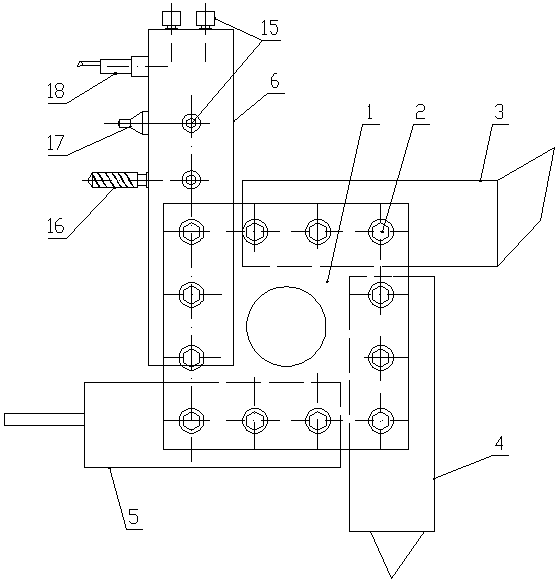
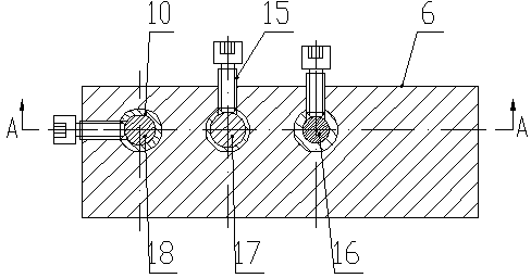
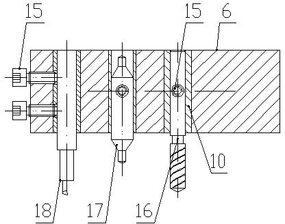
[0021] Such as Figure 1-Figure 9 As shown, the CNC lathe multi-tool position device of the present invention includes an electric square tool rest 1 with four clamping positions, and the three clamping positions of the electric square tool rest 1 are respectively clamped with outer circles by universal compression bolts 2. Turning tool 3, thread turning tool 4 and cutting and grooving turning tool 5, the fourth clamping position of the electric square tool holder 1 is provided with a general-purpose tool installation structure, and the general-purpose tool installation structure includes a general-purpose pressing bolt 2. The body 6 in the shape of a cuboid is clamped, and the body 6 is horizontally provided with a first knife hole 7, a second knife hole 8 and a third knife hole 9 parallel to each other, the first knife hole 7, the second knife hole A bushing 10 is respectively arranged inside the hole 8 and the third tool hole 9, and each bush 10 is respectively equipped wit...


PUM


Abstract

The invention relates to a numerical control lathe multi-cutter-position device. The numerical control lathe multi-cutter-position device comprises a power-driven square cutter rest with four clamping positions, three clamping positions of the power-driven square cutter rest are provided with outer circular turning tool, a threaded turning tool and cutoff groove cutting turning tool in a clamped mode through compression bolts, and the fourth clamping position of the power-driven square cutter rest is provided with a common type cutter installation structure. By means of the numerical control lathe multi-cutter-position device, the time of number of camping of parts is decreased, the auxiliary time for clamping, aligning and the like is shortened, efficiency and the machining accuracy are improved, and the production effect, the practicing effect and the application effect are good. After cutters are additionally arranged, cutter compensation numbers for uniquely identifying the additionally-arranged cutters can be obtained through compensation, calling can be conveniently carried out in the procedure at any time, and the using rate of a numerical control system is increased.

Description

technical field [0001] The invention belongs to the technical field of numerical control machine tools, and in particular relates to a multi-tool position device of a numerical control lathe. Background technique [0002] At present, in the lathe cutting industry, CNC lathes equipped with electric square tool holders can only install four tools at most, and the structure of parts is becoming more and more complex. Whether it is based on machining accuracy or machining efficiency, it is required that the parts should be completed in one clamping. Rough and fine machining at one end requires more than four cutting tools. Moreover, based on the interference between the tools and the collision avoidance with the workpiece during processing, the number of installed tools is even lower than the four tool positions of the machine tool holder. Due to the lack of tool positions, it will lead to secondary clamping of the workpiece, which directly affects the efficiency and accura...

Claims


Application Information

Patent Timeline
IPC IPC(8): B23B21/00
CPCB23B29/26
Inventor 范彩霞王红李会芹杜林豪张海红
Owner 河南华中星科技电子有限公司
Learn More