
A stamping device for a chassis guard plate for an automobile

A chassis guard plate and stamping device technology, which is applied in the direction of presses, safety equipment, metal processing equipment, etc., can solve the problems of being unable to detect whether there are objects or personnel, potential safety hazards of atmospheric pressure devices, and affecting the quality of workpiece forming, etc., to achieve improvement The effect of processing quality, simplification of structure and reduction of equipment cost

Active Publication Date: 2020-03-27
芜湖众梦电子科技有限公司
View PDF1 Cites 0 Cited by
  • Summary
  • Abstract
  • Description
  • Claims
  • Application Information

AI Technical Summary

Problems solved by technology

[0005] (1) There is no protective device, it is impossible to detect whether there are objects or people close to the stamping device, and the stamping device cannot be shut down when the limbs of the personnel extend into the working area of ​​the stamping device, so that there are potential safety hazards in the operation of the atmospheric pressure device;
[0006] (2) When the stamping device stamps and forms the workpiece, it will also be subjected to the reaction force given by the workpiece, resulting in deformation and unable to maintain a horizontal state, which will affect the forming quality of the workpiece

Method used


Image

  • A stamping device for a chassis guard plate for an automobile
  • A stamping device for a chassis guard plate for an automobile
  • A stamping device for a chassis guard plate for an automobile

Examples


Embodiment Construction

[0030] The following will clearly and completely describe the technical solutions in the embodiments of the present invention with reference to the accompanying drawings in the embodiments of the present invention. Obviously, the described embodiments are only some, not all, embodiments of the present invention. Based on the embodiments of the present invention, all other embodiments obtained by persons of ordinary skill in the art without making creative efforts belong to the protection scope of the present invention.

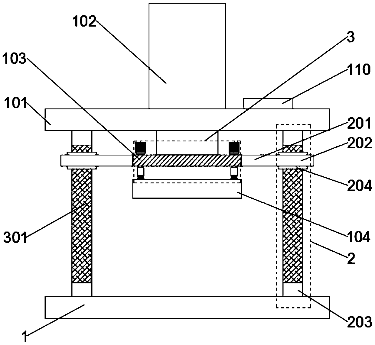
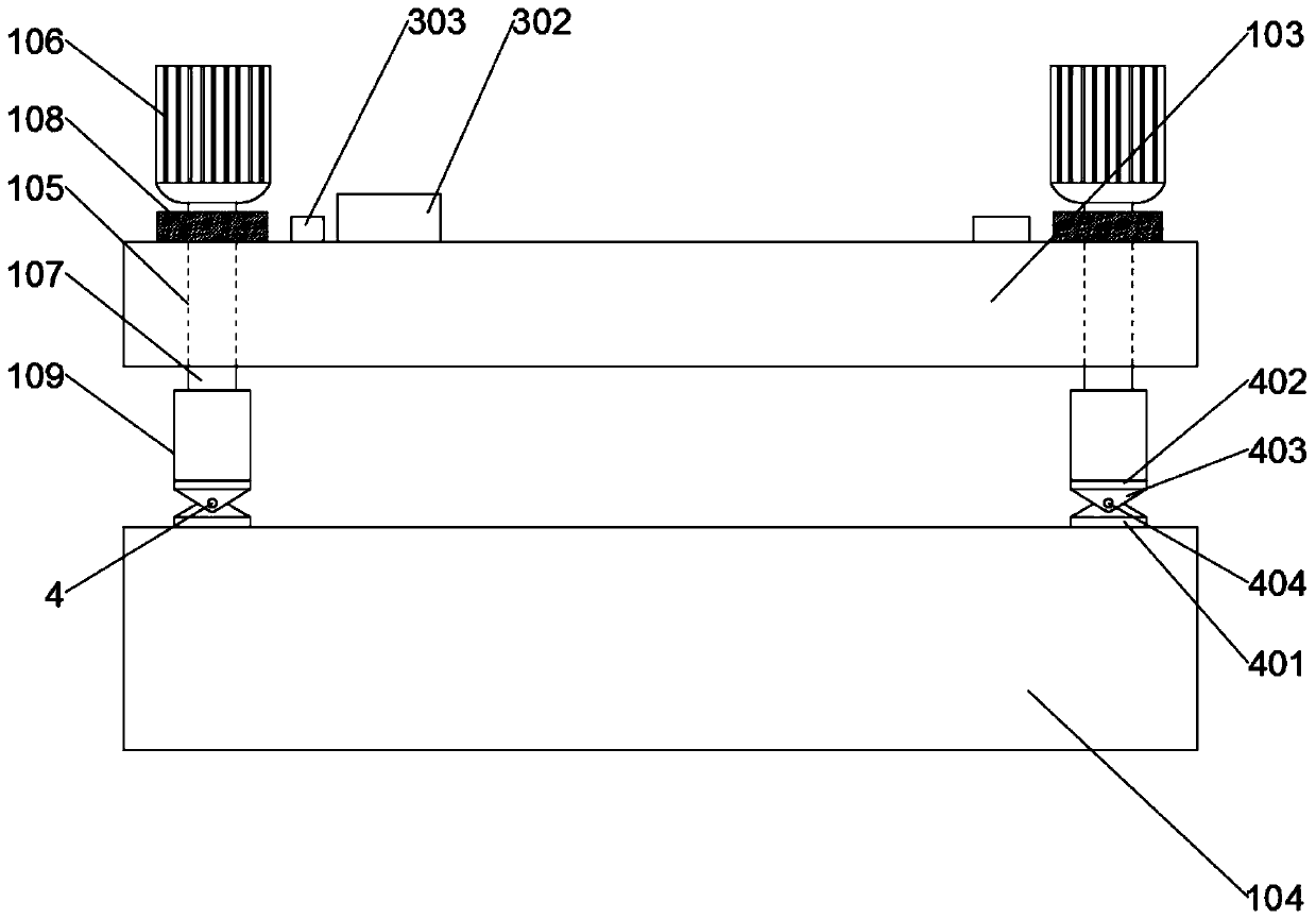
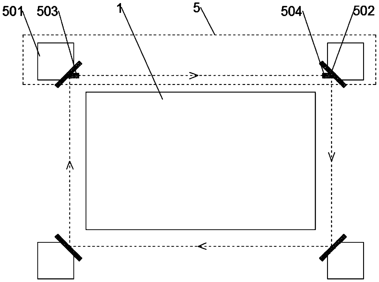
[0031] Such as Figure 1 to Figure 3 As shown, the present invention provides a chassis guard plate stamping device for automobiles, including a workbench 1, a drive installation plate 101 is arranged above the workbench 1, and a drive device 102 is arranged on the drive installation plate 101. The drive device 102 is a hydraulic cylinder, the output end of the hydraulic cylinder passes through the drive installation plate 101 vertically downwards and is conne...


PUM


Abstract

The invention discloses a stamping device for a chassis guarding plate of an automobile. The stamping device comprises a workbench; a driving mounting plate is arranged on the upper portion of the workbench, a driving device is arranged on the driving mounting plate, and the output end of the driving device vertically downwards penetrates through the driving mounting plate and is connected with amounting plate; a stamping plate is arranged on the lower end surface of the mounting plate, a plurality of vertical penetrating fixing holes are formed in the edge of the mounting plate, fixing motors are arranged on the edge of the mounting plate, the number of the fixing holes is equal to that of the fixing motors, fixing rods are rotatably arranged in the fixing holes in a penetrating mode, ananti-stripping ring is arranged on each fixing rod located at the upper end of the corresponding fixing hole, and the output end of each fixing motor is connected with the corresponding fixing rod through a coupling; and the lower ends of the anti-stripping rings are in contact with the upper surface of the mounting plate, and a plurality of vertical positioning cylinders are arranged at the upper end of the stamping plate, and the fixing rods located at the lower ends of the fixing holes are connected within the positioning cylinders in a threaded mode. By means of the stamping device, the structure can be simplified accurately, the equipment cost is reduced, the safety performance is improved, meanwhile, self correcting can be achieved, and the machining quality is improved.

Description

technical field [0001] The invention relates to the technical field of automobile production, in particular to a punching device for chassis guard plates of automobiles. Background technique [0002] Stamping device is a commonly used material processing equipment, which mainly relies on presses and molds to apply external force to plates, strips, pipes and profiles to cause plastic deformation or separation, so as to obtain the required shape and size of the workpiece. processing methods. It is widely used in the lamination of various plates, bricks, and steel materials. The car body, chassis, fuel tank, radiator fins, brake pads, etc. all require stamping processing. The stamping process of the automobile chassis is based on the power of conventional or special stamping equipment, so that the chassis is directly subjected to deformation force and deformed, so as to obtain a certain shape and size. However, the existing stamping devices for automobile chassis still have c...

Claims


Application Information

Patent Timeline
Patent Type & Authority Patents(China)
IPC IPC(8): B21D22/02B21D55/00B30B15/00B30B15/04
CPCB21D22/02B21D55/00B30B15/007B30B15/04
Inventor 张阳姚晓峰李龙
Owner 芜湖众梦电子科技有限公司
Learn More