Multi-joint bionic mechanical chela pincer with autonomous hydraulic power distribution function

A bionic machinery and hydraulic power system technology, applied in the field of intelligent bionic robots, can solve the problems of inconvenient installation and maintenance, single movement mode, less degrees of freedom, etc., to reduce external energy requirements, easy installation and disassembly, and reduce complexity. Effect

Pending Publication Date: 2018-10-30
长沙紫宸科技开发有限公司
View PDF9 Cites 3 Cited by
  • Summary
  • Abstract
  • Description
  • Claims
  • Application Information

AI Technical Summary

Problems solved by technology

[0006] In the 12th issue of "Mechanics and Electronics" in 2009, a paper titled "Design and Realization of Bionic Crab Robot" was published. The robot has 2 claws, and each claw has 3 joints, which are respectively driven by 3 servo motors, which can realize the functions of picking up and transporting bionic crabs; but this type of bionic claws has the following problems: First, it is only suitable for light or Light-loaded robots generally use small or light servo motors and reducers, resulting in small clamping force and bearing capacity, which cannot be applied to large or heavy-duty bionic robots. Second, this type of bionic claw has no self-powered , the power is concentrated on the main frame of the robot, which needs to be transported to the bionic pincers through the cable, and it is easy to be paralyzed due to the wear and tear of the connecting cable due to frequent movement; the third is the long charging time and low charging efficiency of its integral centralized power supply, and the fourth This kind of bionic pliers is connected to the power on the main frame, so installation and maintenance are mostly inconvenient
[0007] CN201610277479.2 discloses a multipurpose bionic crab robot, which includes a right clamp module and a left clamp module; the right clamp module is driven by a right clamp drive motor, a right clamp drive pinion, a right clamp drive gear, Right tong swivel arm, right tong primary drive hydraulic lever, right pivot pin, right tong primary drive arm, right tong secondary drive hydraulic lever, right tong secondary drive arm, right Side clamp third-stage drive hydraulic rod, right clamp third-stage drive arm, rotary cutting blade, auxiliary camera, flat-blade automatic screwdriver, cross automatic screwdriver, rotary cutting blade driving eccentric disk, rotary cutting blade driving disc motor, rotary The cutting blade drives the first connecting rod, the rotary cutting blade drives the second connecting rod, and the rotary cutting knife teeth; the left clamp module adopts a similar structure to realize the function of stretching the saw blade; this patent uses mechanical and hydraulic methods to realize the sawing of bionic chelicer branches It has the characteristics of large clamping force and strong sawing ability, but it has the following defects: First, the power source is concentrated on the main frame of the bionic machine, and the hydraulic power system on the main frame of the robot needs to provide the joints of the claws. Hydraulic power is easily paralyzed due to wear and tear caused by frequent movement of connecting cables or hydraulic pipes; second, its integrated centralized power supply is arranged on the main body of the bionic robot, which has the problems of long charging time and low charging efficiency; third, the use of straight lines The joint motion of the oil cylinder and the driver present a nonlinear relationship, which leads to a complex control system; Fourth, the bionic pliers and the connecting cables or / and hydraulic pipes arranged in it must be directly connected to the main frame of the robot, which is extremely inconvenient to disassemble
[0008] CN201410581468.4 discloses a bionic crab robot, wherein the pincer system includes a rack, and a pincer main body is respectively installed at a symmetrical position on the left and right sides of the rack, and each pincer main body is composed of a fixed frame, a motor frame , swing steering gear, two connecting cards, tray, grasping steering gear, two key-shaped gear rods, two claw rods and two connecting rods. This patent uses the mechanical method of the connecting rod mechanism to realize the pliers The clamping function has the following problems: First, the power source is concentrated on the main frame of the bionic machine, and the mechanical structure of multiple parts is used to transmit power, which is complicated in structure and poor in reliability; second, the movement mode is single and there are few degrees of freedom. The ability to adapt to complex working conditions is poor; the third is that its integrated centralized power supply is arranged on the main body of the bionic robot, which has the problems of long charging time and low charging efficiency; fourth, it is inconvenient to install and maintain

Method used


Image

  • Multi-joint bionic mechanical chela pincer with autonomous hydraulic power distribution function
  • Multi-joint bionic mechanical chela pincer with autonomous hydraulic power distribution function
  • Multi-joint bionic mechanical chela pincer with autonomous hydraulic power distribution function

Examples


Embodiment 1

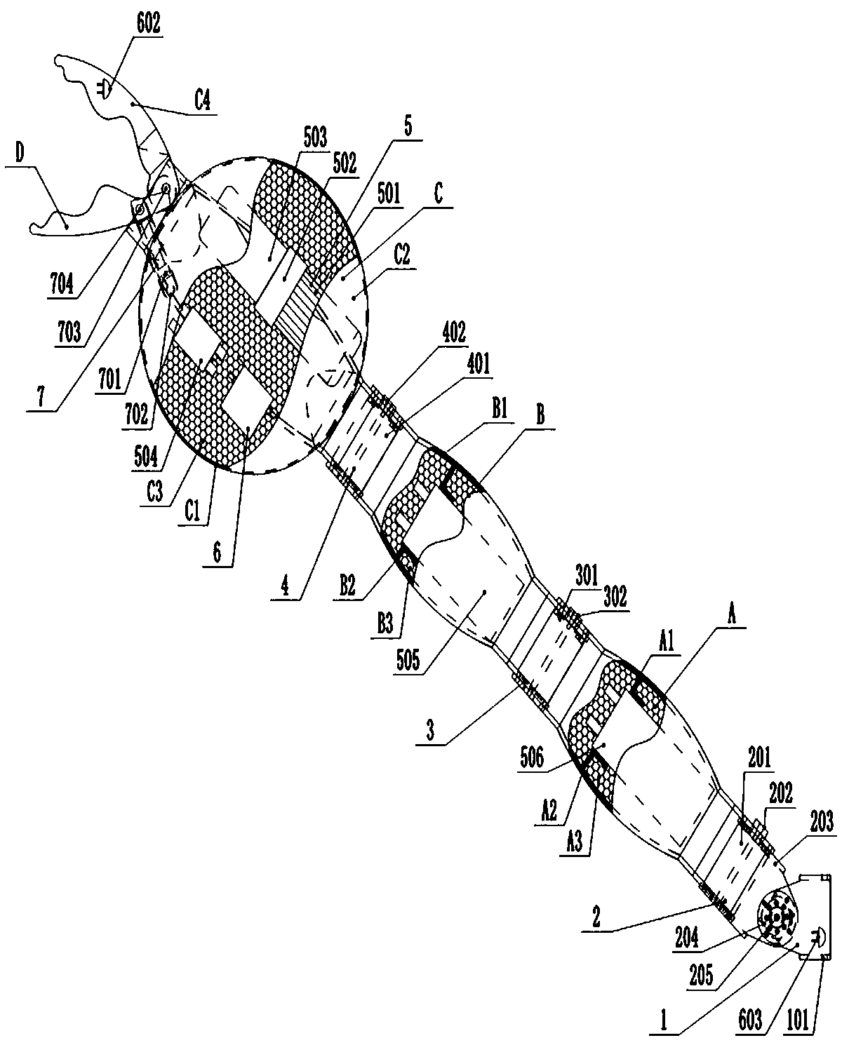
[0032] refer to figure 1 , figure 2 In this embodiment, the multi-joint bionic mechanical pliers with independent hydraulic power distribution mainly includes a connecting frame 1, a three-dimensional joint 2, a claw joint A, a two-dimensional joint I3, a claw joint B, a two-dimensional joint II4, a claw-shield joint C, Clamp moving device 7, clamp joint D, integrated hydraulic power system 5, intelligent electric control device 6; the three-dimensional joint 2 is fixed on the connecting frame 1 and connected with the jaw joint A, and the jaw joint A is connected with the jaw joint B through the two-dimensional joint I3 , the chela-shield B is connected with the chela-shield C through the two-dimensional joint II4, and the chela-shield C is connected with the chela-shield D through the clamp device 7, and the integrated hydraulic power system 5 is fixed on the claw A, the claw B and the claw-shield C In the cavity, it is respectively connected with the hydraulic ports of the...

Embodiment 2

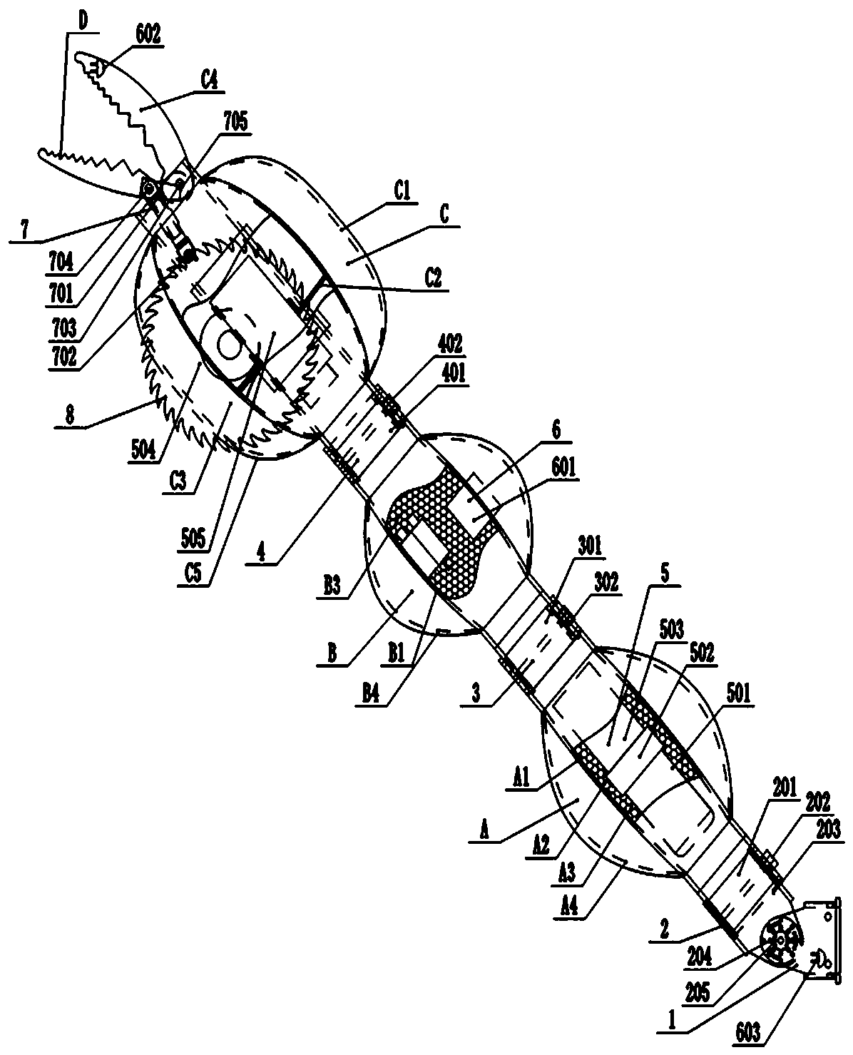
[0040] refer to image 3 , Figure 4 , the multi-joint bionic mechanical pincers with independent hydraulic power distribution in this embodiment differs from Embodiment 1 only in that: the mechanical pincers are additionally provided with a circular saw 8, which is fixed at the middle and lower part of the pincer-shield joint C; The connecting frame 1 adopts the form of a card slot and a fixed pin hole for quick connection; the claw joint A and the claw joint B are special-shaped components made of titanium alloy with cavities; wherein the outer surfaces of the claw joint A and the claw joint B are also provided with There are solar film parts ⅠA4 and solar film parts ⅡB4, which are used to collect solar energy to supply power to the bionic legs; the ends of the claw joint A and the claw joint B are provided with elastic stretchable protective sleeves A5 and elastic stretchable protective sleeves B5 for joint protection; the claw joints The shield section C adopts a shield s...

Embodiment 3

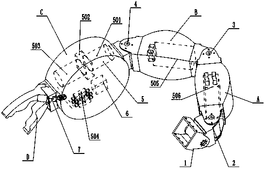
[0042] refer to Figure 5 , Image 6 , the difference between the multi-joint bionic mechanical pliers with independent hydraulic distribution power in this embodiment and embodiment 1 is only that a chain saw 8 is added on the mechanical pliers, which is fixed in the middle part of the claw-shield joint C; the chain saw 8 includes a drive motor 801, a chain saw disc 802, and a swing cylinder 803, wherein the swing cylinder 803 controls the swing of the chain saw disc 802, and when the chain saw is not working, the chain saw disc swings to the side of the upper jaw C4. The upper clamp section C4 and the clamp section D form a clamp, which is driven by the clamp hydraulic cylinder 701 to clamp the object, and is sawed off with the chain saw 8; the power device 5 is arranged in the claw section A, and Claw-shield joint C adopts shield type.


PUM


Abstract

A multi-joint bionic mechanical chela pincer with an autonomous hydraulic power distribution function comprises a chela joint, a three-dimensional joint, a two-dimensional joint, a chela shield jointand a pincer joint and is further provided with a connecting frame, a pincer moving device, integrated hydraulic power systems and intelligent electric control devices. The three-dimensional joint isfixed to the connecting frame and connected with the chela joint. The chela joint is connected with the chela shield joint through the two-dimensional joint. The chela shield joint is connected with the pincer joint through the pincer moving device. The integrated hydraulic power systems are fixed into a cavity / cavities of the chela joint or / and the chela shield joint and connected with hydraulicconnectors of the three-dimensional joint, the two-dimensional joint and the pincer moving device through hydraulic pipelines correspondingly. The intelligent electric control devices are fixed into acavity / cavities of the connecting frame or / and the chela joint or / and the chela shield joint and electrically connected with the integrated hydraulic power systems, the three-dimensional joint, the two-dimensional joint and the pincer moving device correspondingly. The multi-joint bionic mechanical chela pincer is simple in structure, convenient to disassemble and assemble, large in joint torqueand high in charging efficiency.

Description

technical field [0001] The invention relates to the technical field of intelligent bionic robots, in particular to a multi-joint bionic pincer with autonomous hydraulic power distribution. Background technique [0002] With the needs of production and the development of science and technology, since the 1950s, people have realized that the biological system is one of the main ways to develop new technologies, and consciously regard the biological world as a variety of technical ideas, design principles and inventions. source of. People use chemical, physical, mathematical and technical models to carry out in-depth research on biological systems, which promotes the great development of biology, and the research on the functional mechanism of living organisms has also made rapid progress. Begin to use the knowledge gained from the biological world to improve old or create new engineering and technological devices. Biology began to step into the ranks of technological innovat...

Claims


Application Information

Patent Timeline
Patent Type & Authority Applications(China)
IPC IPC(8): B25J17/00B25J17/02B25J15/00B25J19/00B25J9/00B25J9/16
CPCB25J9/00B25J9/0009B25J9/16B25J15/00B25J17/00B25J17/02B25J19/00
Inventor 尹小林韩建英
Owner 长沙紫宸科技开发有限公司
Why Eureka
Try Eureka