Multi-joint bionic diploe with autonomous hydraulic distribution power

A hydraulic power system and multi-joint technology, applied in the field of intelligent bionic robots, can solve the problems of inability to realize multi-angle motion, low charging efficiency, inconvenient disassembly and assembly, etc., and achieve rapid disassembly and replacement, simple structure, and improved work reliability. Effect

Pending Publication Date: 2018-10-26
长沙紫宸科技开发有限公司
View PDF7 Cites 6 Cited by
  • Summary
  • Abstract
  • Description
  • Claims
  • Application Information

AI Technical Summary

Problems solved by technology

This technical solution has the following defects: First, the power source is concentrated on the main frame of the bionic machine, and the power system on the main frame of the robot needs to provide power for the tail, which is easily paralyzed due to wear and tear caused by frequent movement of connecting cables or hydraulic pipes; Second, its integral centralized power supply is arranged on the main body of the bionic robot, which has the problems of long charging time and low charging efficiency; third, the connecting cables or / and hydraulic pipes required for the joints of the bionic tail must be directly connected to the main frame of the robot. connected, it is extremely inconvenient to disassemble and assemble; fourth, its tail is mainly used to complete the function of photographing and investigation, and has a single function; fifth, the range of motion of multi-joints is flat, and multi-angle motion cannot be realized

Method used


Image

  • Multi-joint bionic diploe with autonomous hydraulic distribution power
  • Multi-joint bionic diploe with autonomous hydraulic distribution power
  • Multi-joint bionic diploe with autonomous hydraulic distribution power

Examples


Embodiment 1

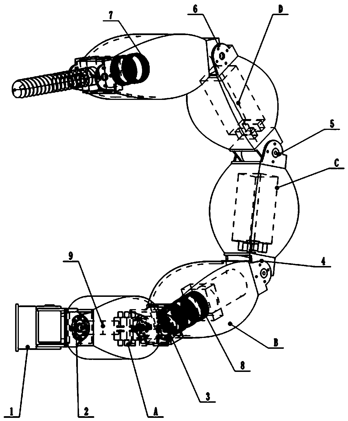
[0036] refer to figure 1 , figure 2 , the multi-joint bionic scorpion tail with autonomous hydraulic distribution power in this embodiment includes a connecting frame 1, a three-dimensional joint 2, a tail section A, a two-dimensional joint I3, a tail section B, a two-dimensional joint II4, a tail section C, and a two-dimensional joint III5, tail section D, two-dimensional joint IV6, tail spur device 7, hydraulic power system 8 and electronic control device 9; three-dimensional joint 2 is fixed on the connecting frame 1 and connected with tail section A, tail section A, tail section B, The tail section C, the tail section D and the tail thorn device 7 are sequentially connected through the two-dimensional joint I3, the two-dimensional joint II4, the two-dimensional joint III5, and the two-dimensional joint IV6, and the hydraulic power system 5 is fixed on the tail section A, the tail section B, and the two-dimensional joint. The cavities of tail section C and tail section D ...

Embodiment 2

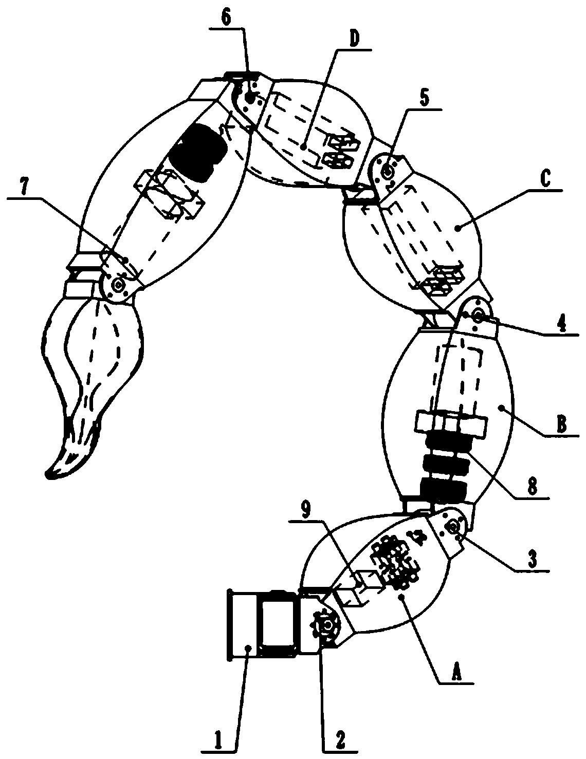
[0043] refer to image 3 , Figure 4 , the multi-joint bionic scorpion tail with autonomous hydraulic distribution power in this embodiment is only different from the embodiment 1 in that the tail section A, tail section B, tail section C and tail section D are made of aluminum alloys to make special-shaped shapes with cavities Components, each tail section is provided with anti-shock vibration damping material parts to reduce the impact damage when attacked. The swinging cylinder 706 and the spraying tail 707, wherein the tail piercing device 7 can spray medicine on the enemy and pierce the body of the enemy to inject medicine when receiving an attack command.

Embodiment 3

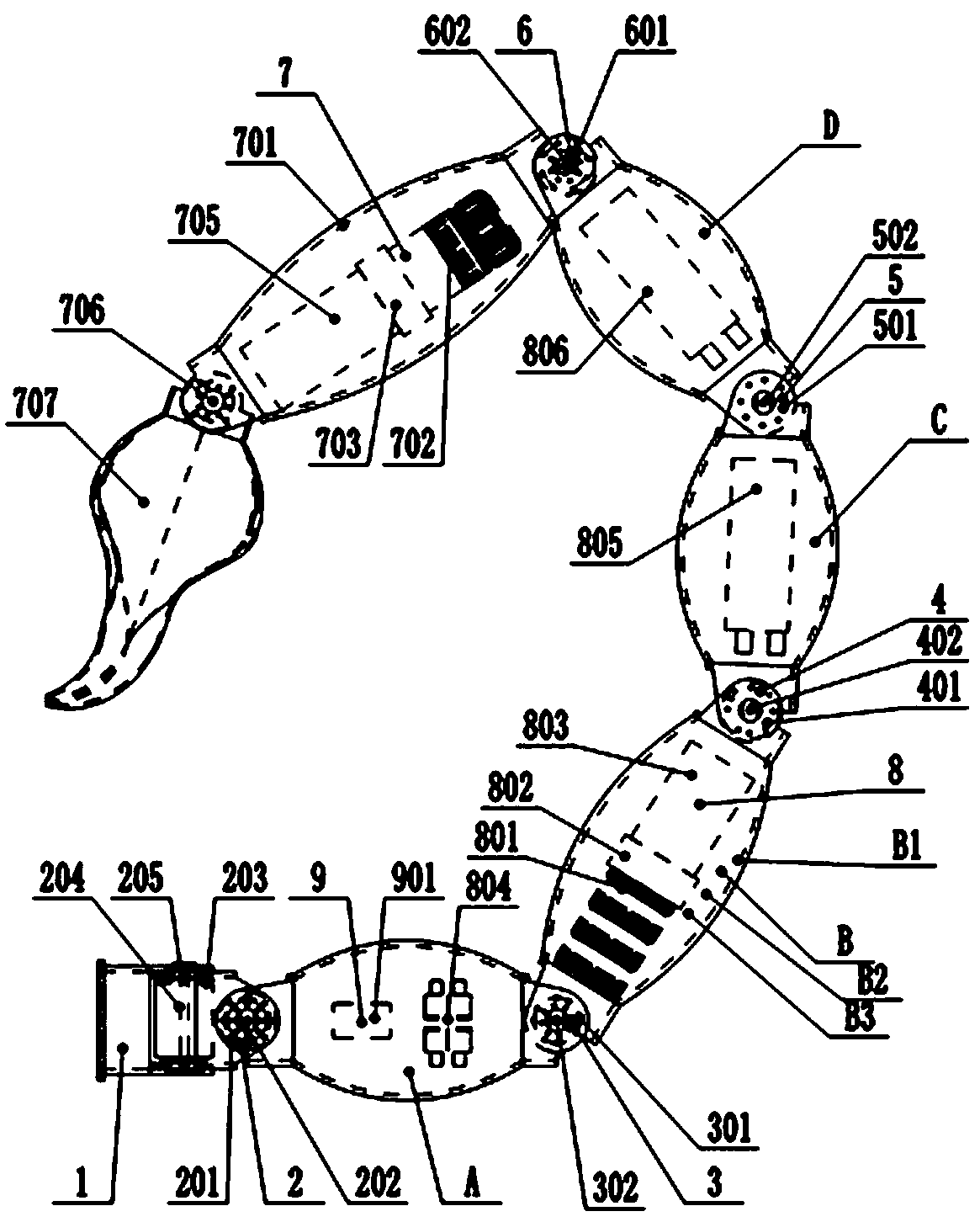
[0045] refer to Figure 5 , Image 6 , Figure 7 , the difference between the multi-joint bionic scorpion tail with autonomous hydraulic power distribution in this embodiment and the embodiment 1 is only that the connecting frame 1 adopts the form of fixed pin holes for quick connection; the tail section A, tail section B, tail section C and The tail section D is made of titanium alloy as a special-shaped component with a cavity, wherein the surface of the tail section B is provided with a solar film member B4 for collecting solar energy. The drive motor 801, the hydraulic pump 802 and the micro fuel tank 803 are arranged in the cavity of the tail section D, the hydraulic solenoid valve group 804 and the controller 901 are arranged in the cavity of the tail section B, and the battery pack I 805 and the battery pack II 806 are arranged in the tail section. Section A and tail section C. The tail thorn device 7 adopts a laser-generated lotus tail thorn structure, which mainly ...


PUM


Abstract

A multi-joint bionic diploe with autonomous hydraulic distribution power comprises a connecting frame and tail joints. A three-dimensional joint, a two-dimensional joint, a caudal spine device, a hydraulic power system and an electronic control device are further arranged, the number of the tail joints is larger than or equal to 4, and the three-dimensional joint is fixed to the connecting frame and connected with the tail joints. The tail joints are connected end to end by the two-dimensional joint, the caudal spine device is connected with that tail joint through the two-dimensional joint,the hydraulic power system is fixed in the cavity of the tail joint, and is respectively connected with the hydraulic interfaces of the three-dimensional joint, the two-dimensional joint and the caudal spine device through hydraulic pipelines. The electric control device is fixed in the cavity of the connecting frame or/and the tail joint or/and the caudal spine device, and the electric controldevice is respectively electrically connected with the hydraulic power system, the three-dimensional joint, the two-dimensional joint and the caudal spine. The invention has a simple structure and isconvenient to install and disassemble. The advantage of low failure rate, high reliability and high bearing capacity make it convenient for bionic mechanical scorpion to be used in earthquake rescue,security protection, military reconnaissance and field exploration.

Description

technical field [0001] The invention relates to the technical field of intelligent bionic robots, in particular to a multi-joint bionic scorpion tail with autonomous hydraulic distribution power. Background technique [0002] With the needs of production and the development of science and technology, since the 1950s, people have realized that biological systems are one of the main ways to open up new technologies, and consciously regard the biological world as a variety of technical ideas, design principles and inventions. the source of. People use chemical, physical, mathematical and technical models to carry out in-depth research on biological systems, which has promoted the great development of biology, and the research on the functional mechanism of living organisms has also made rapid progress. Begin to use the knowledge gained from the biological world to improve old or create new engineering and technical equipment. Biology began to step into the ranks of technologi...

Claims


Application Information

Patent Timeline
Patent Type & Authority Applications(China)
IPC IPC(8): B25J9/06B25J17/00B25J17/02B25J19/00B25J9/00H02J7/35
CPCH02J7/35B25J9/00B25J9/0009B25J9/06B25J17/00B25J17/02B25J17/0258B25J17/0283B25J19/00
Inventor 尹小林韩建英
Owner 长沙紫宸科技开发有限公司
Why Eureka
Try Eureka