Gear synchronous displacement modular expansion joint

A technology of synchronous displacement and expansion joints, applied to bridge parts, bridges, buildings, etc., can solve the problems of easy damage, uneven force, etc., and achieve the effect of convenient maintenance and disassembly, low cost and long life

Active Publication Date: 2018-10-30
曹志强
View PDF6 Cites 10 Cited by
  • Summary
  • Abstract
  • Description
  • Claims
  • Application Information

AI Technical Summary

Problems solved by technology

[0004] The technical problem to be solved by the present invention is to provide a gear synchronous displacement modulus expansion joint. The device has a simple structure, is easy to maintain and disassemble, is stable and has a good shockproof effect, and the cooperation of the rack and the gear in the sliding connection

Method used


Image

  • Gear synchronous displacement modular expansion joint
  • Gear synchronous displacement modular expansion joint
  • Gear synchronous displacement modular expansion joint

Examples


Embodiment 1

[0030] Example 1 A Gear Synchronous Displacement Modular Expansion Joint

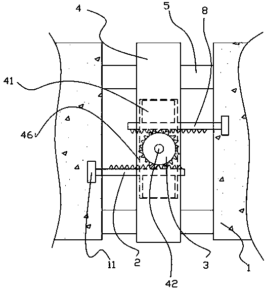
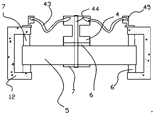
[0031] This embodiment is a gear synchronous displacement modular expansion joint, which is installed in the gap between two existing bridge bodies 1, such as figure 1 As shown, it comprises the bridge main bodies 1 that are set apart, namely the left and right bridge body main bodies 1 in the figure, the middle is an expansion gap, and the bottom of the left and right bridge body main bodies 1 is respectively provided with displacement boxes 12 (beam body main body 1, The displacement boxes 12 are existing devices, and the positional relationship between them and the connection mode are also existing technologies), and two relative displacement boxes 12 are provided with a bridge spanning the expansion gap between the two bridge main bodies 1. The horizontal beam 5 extending along the length direction of the bridge body 1 can be provided with a plurality of displacement boxes 12 and beams 5 according t...

Embodiment 2

[0038] Embodiment 2 A gear synchronous displacement modular expansion joint

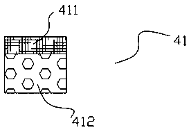
[0039] This embodiment is a gear synchronous displacement modular expansion joint, the specific structure is similar to that of Embodiment 1, the only difference is that it includes two or more sets of expansion joint sliding connection devices connected in series, that is, it includes two or more sets The first rack 2, the ball bearing 42, the second rack 8, and the gear 3. In practical applications, when the expansion gap is large, several middle beams 4 need to be provided, and the lower surface of each middle beam 4 is provided with a gear protection box 46, and the gear protection box 46 is provided with a first rack 2, a ball bearing 42. The second rack 8, the gear 3 and the buttress 41, a rack is shared between two adjacent middle beams 4, and each middle beam 4 is equipped with a gear 3, and two or more sets of them are connected in series. When the expansion joint slides the connection devi...


PUM


Abstract

The invention discloses a gear synchronous displacement modular expansion joint which comprises bridge main bodies arranged at intervals, a displacement box fixedly arranged at the lower part of the two bridge main bodies, a horizontal cross beam which extends across the gap between the main bodies of the bridge along the length direction of the bridge main body arranged between the two relative displacement boxes; the cross beam is provided with a middle beam which is perpendicular to the cross beam and extends along the width direction of the bridge main body; the lower surface of the middlebeam is fixedly provided with a gear protection box, an expansion joint sliding connection device is arranged in the gear protection box, and two ends of the expansion joint sliding connection deviceare respectively fixedly connected with a rack fixing part embedded in the bridge main body. The device has the advantages of simple structure, convenient maintenance and disassembly, and the expansion joint sliding connection device can realize the free expansion and contraction movement of the expansion joint when the stress of the two ends of the bridge main body is not uniform, and the problem of easy damage due to uneven stress is overcome. The gear synchronous displacement modular expansion joint is suitable for use as a connecting device in a bridge expansion joint.

Description

technical field [0001] The invention belongs to the field of bridge expansion joint devices, and relates to a gear synchronous displacement modular expansion joint. Background technique [0002] The bridge telescopic device is an important part connecting the two parts of the bridge body. Its functions in terms of load bearing, expansion and contraction, and waterproof will directly affect the overall life of the bridge. The existing expansion joint device is a cross structure. When the bridge body expands with heat and contracts with cold, it will drive the four-bar linkage device to shrink or relax. However, in this structure, the two ends of the bridge body drive the cross structure and The fulcrums of the four links connected to the bridge body are compressed or expanded. When the force on both ends of the bridge body is uniform, the force on each fulcrum of the four links is uniform. When the force on the bridge body is uneven, it is easy to cause a point of the four li...

Claims


Application Information

Patent Timeline
IPC IPC(8): E01D19/06
CPCE01D19/06
Inventor 曹志强
Owner 曹志强
Why Eureka
Try Eureka