Air conditioner indoor unit and air conditioner

A technology for air-conditioning indoor units and appliances, which is applied to air-conditioning systems, space heating and ventilation, space heating and ventilation details, etc. The effect of wind distance, improved air output and energy efficiency

Pending Publication Date: 2018-10-30
GD MIDEA AIR-CONDITIONING EQUIP CO LTD +1
0 Cites 0 Cited by

AI-Extracted Technical Summary

Problems solved by technology

[0004] The main purpose of the present invention is to provide an air-conditioning indoor unit...

Method used

The technical scheme of the present invention is by setting the fin of heat exchanger 13 to be zigzag, and the first water receiving tank 14a that the water receiving tray 14 is arranged in a plurality of intervals, the adjacent two first water receiving tanks 14a The bracket has an air vent 140. When the air conditioner indoor unit 10 is running, external air can enter the casing 11 through the air vent 140 and exchange heat with the heat exchanger 13. The condensed water formed on the surface of the heat exchanger 13 can drip along the tooth protrusions 13a falls into the first water receiving tank 14a, so that the water receiving tray 14 can pass the wind and receive water, thereby reducing the wind resistance of external air entering the air conditioner indoor unit 10, improving the air output and energy efficiency, and further improving the The air supply distance of the air-conditioning indoor unit 10 improves the effect of warming feet.
[0046] The heat exchanger 13 is arranged in the shell 11, the ...

Abstract

The invention discloses an air conditioner indoor unit and an air conditioner. The air conditioner indoor unit comprises a shell, a heat exchanger and a water receiving disc; the shell is provided with a front panel and a back panel; the heat exchanger is arranged in the shell, the heat exchanger is provided with a plurality of fins, and the lower ends of the fins are arranged in a zigzag shape; the water receiving disc is installed between the front panel and the back panel and is positioned below the heat exchanger, and the water receiving disc is provided with a plurality of first water receiving grooves which are arranged at intervals; and the first water receiving grooves are located below tooth protrusions of the heat exchanger so as to receive condensed water falling from the toothprotrusions, and an air passing port is formed between every two adjacent first water receiving grooves. According to the technical scheme, the air inlet resistance is reduced, and the air outlet volume and the air supply distance are increased.

Application Domain

Condensate preventionAir conditioning systems +1

Technology Topic

Condensed waterAir volume +4

Image

  • Air conditioner indoor unit and air conditioner
  • Air conditioner indoor unit and air conditioner
  • Air conditioner indoor unit and air conditioner

Examples

  • Experimental program(1)

Example Embodiment

[0039] The following will clearly and completely describe the technical solutions in the embodiments of the present invention with reference to the accompanying drawings in the embodiments of the present invention. Obviously, the described embodiments are only part of the embodiments of the present invention, not all of them. Based on the embodiments of the present invention, all other embodiments obtained by persons of ordinary skill in the art without creative efforts fall within the protection scope of the present invention.
[0040] It should be noted that all directional indications (such as up, down, left, right, front, back...) in the embodiments of the present invention are only used to explain the relationship between the components in a certain posture (as shown in the accompanying drawings). Relative positional relationship, movement conditions, etc., if the specific posture changes, the directional indication will also change accordingly.
[0041] In addition, the descriptions involving "first", "second" and so on in the present invention are only for descriptive purposes, and should not be understood as indicating or implying their relative importance or implicitly indicating the quantity of the indicated technical features. Thus, the features defined as "first" and "second" may explicitly or implicitly include at least one of these features. In addition, the technical solutions of the various embodiments can be combined with each other, but it must be based on the realization of those skilled in the art. When the combination of technical solutions is contradictory or cannot be realized, it should be considered that the combination of technical solutions does not exist , nor within the scope of protection required by the present invention.
[0042] The present invention provides an air-conditioning indoor unit and an air conditioner including the air-conditioning indoor unit. The air-conditioning indoor unit may be a wall-mounted or ceiling-mounted indoor unit. With regard to the air conditioner indoor unit, the following content of the ceiling-mounted indoor unit is introduced as a specific embodiment.
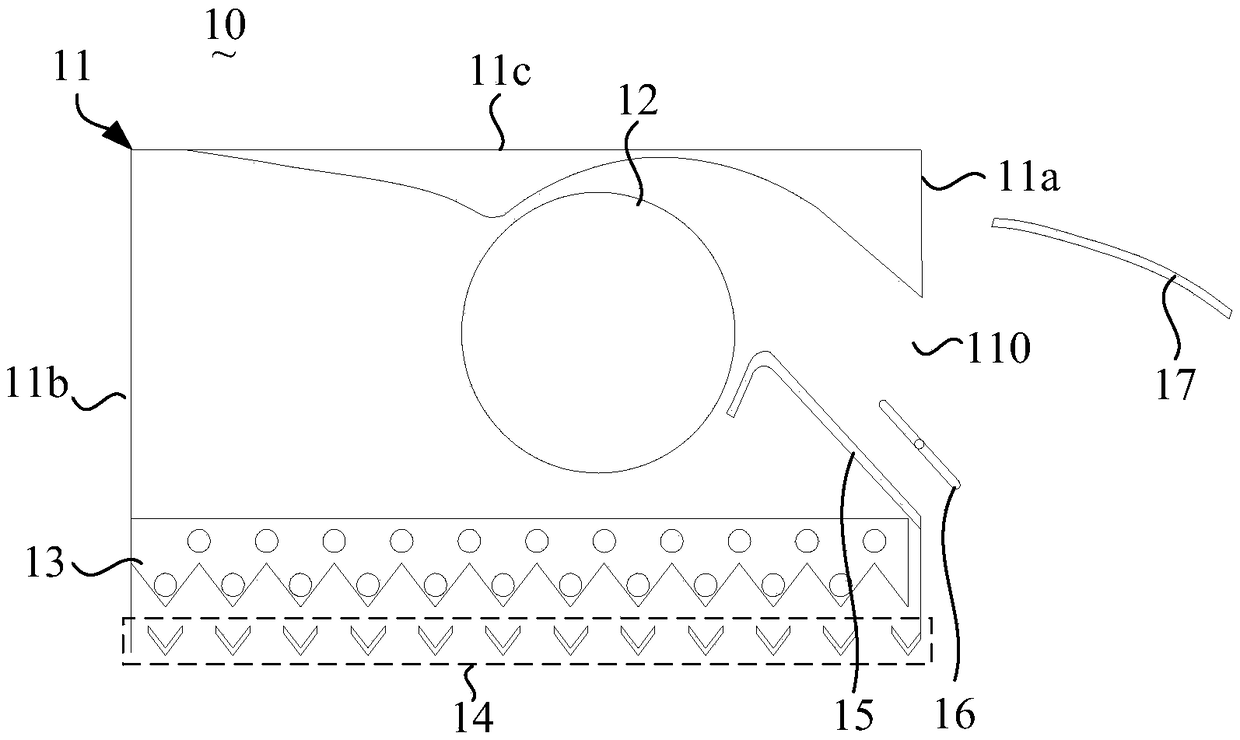
[0043] see figure 1 and image 3 , the present invention proposes an air conditioner indoor unit 10 , the air conditioner indoor unit 10 has a casing 11 , a volute assembly 15 , a wind wheel 12 , a heat exchanger 13 and a water tray 14 . Wherein, the housing 11 has a front panel 11a, a rear panel 11b, a left panel (not shown), a right panel (not shown) and a top panel 11c, the front panel 11a may be provided with an air outlet 110, of course , the air outlet 110 can also be arranged on the bottom plate (provided that the housing 11 has a bottom plate).
[0044] The volute assembly 15 is formed with an air outlet channel, and the air outlet channel communicates with the air outlet 110 . A first air deflector 16 is installed at the air outlet 110, so that the air outlet angle can be adjusted. A second wind deflector 17 is also installed on the panel. On the one hand, the second wind deflector 17 can be rotated to further adjust the wind outlet angle. On the other hand, when the air conditioner stops running, the second wind deflector 17 The wind plate 17 can also cover the air outlet 110 to prevent dust or other sundries from entering.
[0045] The wind wheel 12 may be a cross flow wind wheel 12 , an axial flow wind wheel 12 or a centrifugal wind wheel 12 . Here, considering the noise problem on the one hand, and the thinner design of the air conditioner indoor unit 10 on the other hand, the type of the wind wheel 12 is preferably a cross-flow wind wheel 12 .
[0046]The heat exchanger 13 is disposed in the housing 11, and the heat exchanger 13 has a plurality of fins arranged side by side, and the lower ends of the fins are arranged in a zigzag shape. For the tooth protrusions 13a of each fin, a plurality of tooth protrusions 13a may be arranged along the same straight line, or along a curved line, or even randomly. Here, the function of the tooth protrusion 13 a is mainly to collect condensed water, and the accumulated condensed water can drip downward from the tooth protrusion 13 a. For the arrangement of the tooth protrusions 13a, the preferred way is: the tooth protrusions 13a located on multiple fins and adjacent to each other are arranged in a straight line, so that it is convenient for the manufacturing and shaping of the fins, and it is also convenient for the water tray 14 for the collection of condensed water.
[0047] The water receiving tray 14 is installed between the front panel 11a and the back panel 11b, and is located below the heat exchanger 13, and the water receiving tray 14 has a plurality of first water receiving tanks 14a arranged at intervals , the first water receiving tank 14a is located below the tooth protrusion 13a of the heat exchanger 13 to receive the condensed water dripping from the tooth protrusion 13a, and there is formed between two adjacent first water receiving tanks 14a Air outlet 140.
[0048] Here, the heat exchanger 13 may be a two-fold heat exchanger, or a three-fold heat exchanger, or a flat heat exchanger. The shape of the heat exchanger 13 can be arranged in a V shape (two-fold heat exchanger), or roughly in a U-shaped arrangement (three-fold heat exchanger). As long as the lower surface of the fins is provided in a sawtooth shape, the tooth protrusions 13 a can collect condensed water and drop the condensed water into the water receiving tray 14 .
[0049] In the technical solution of the present invention, the fins of the heat exchanger 13 are arranged in a zigzag shape, and the water receiving tray 14 is arranged as a plurality of first water receiving tanks 14a arranged at intervals, and the adjacent two first water receiving tanks 14a brackets have excessive The tuyere 140, when the air conditioner indoor unit 10 is running, outside air can enter the interior of the casing 11 through the air outlet 140, and exchange heat with the heat exchanger 13, and the condensed water formed on the surface of the heat exchanger 13 can drop along the tooth protrusion 13a to the second One water receiving tank 14a, so that the water receiving tray 14 can not only pass through the wind, but also receive water, thereby reducing the wind resistance of external air entering the air-conditioning indoor unit 10, improving the air output and energy efficiency, and further improving the air-conditioning indoor unit. The air supply distance of 10 improves the effect of warming feet.
[0050] Please continue to refer to figure 1 , in the above embodiment, the housing 11 may have a bottom plate or may not have a bottom plate. For the situation with a bottom plate, the bottom plate can be four wall panels (front panel 11a, rear back panel 11b, left side panel and right side panel) connected to the shell 11, the bottom plate has a partial opening, and the water receiving tray 14 is arranged at the opening. And the water receiving tray 14 is fixed on the base plate. Of course, in this case, the manufacturing cost of the air conditioner indoor unit 10 is relatively high, and the assembly is complicated. In view of this, in a preferred embodiment, the housing 11 adopts a situation without a bottom plate. That is to say, the lower port of the casing 11 is covered by the water tray 14 (the water tray 14 is connected to the four wall panels of the casing 11), so that the casing 11 does not have a bottom plate, and the water tray 14 covers the lower port of the casing 11. All are covered, so, for the air-conditioning indoor unit 10, the structure is simple and the assembly is convenient.
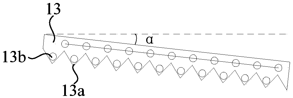
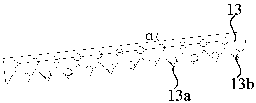
[0051] The above embodiments do not limit the structure of the heat exchanger 13 . Considering that the two-fold and three-fold heat exchangers are not conducive to the thinning of the overall height of the air conditioner indoor unit 10, there are also higher requirements for the tooth protrusions 13a. In view of this, in this embodiment, please refer to FIG. 2 , the heat exchanger 13 extends from the front panel 11a toward the rear panel. That is to say, the heat exchanger 13 is arranged in a plate shape. For the heat exchanger 13, the angle α ∈ [0, 30°] with the horizontal plane, α=0°, 5°, 10°, 15° °, 25°, 30° are all possible. For example, the heat exchanger 13 is arranged inclined backward, and its inclination angle is α.
[0052] Of course, if α=0°, the heat exchanger 13 is arranged along the horizontal direction, which is most conducive to the thinning of the air conditioner indoor unit 10 . In addition, in order to make the contact area between the heat exchanger 1313 and the air larger, α may be adjusted appropriately, such as α=5°, 7° or 10°.
[0053] see image 3 and Figure 4 , for the side surface of the tooth protrusion 13a, if the included angle with respect to the horizontal plane is less than 45°, there will be a phenomenon of condensed water dripping directly, and the dripped condensed water will leak from the air outlet 140, seriously affecting the user experience .
[0054] In view of this, in this embodiment, one side surface of the tooth protrusion 13a is cut into an upper side 131 and a lower side by the upper edge of the first water receiving groove 14a located below the side surface on a vertically upward projection line 132, the angle between the upper side surface 131 and the horizontal plane is β. For β, if it is too large, too many tooth protrusions 13a need to be provided, and if it is too small, the drainage effect will be reduced. Here, β∈[45°, 75°].
[0055] It is considered that if the included angle between the upper side surface 131 and the horizontal plane is too small, the drainage effect will be reduced, but at the same time, it will contribute to the thinning of the entire air conditioner indoor unit 10 .
[0056] Different from the above embodiment, in this embodiment, please refer to Image 6 , the angle between the upper side 131 and the horizontal plane is γ, γ∈[0°, 45°); a second water receiving tank 14b is arranged below the air outlet 140, and the first water receiving tank 14a and the second water receiving tank 14a A wind clearance gap 141 is reserved between the water receiving tanks 14b.
[0057] Here, the disadvantage of water leakage caused by the small angle between the upper side surface 131 and the horizontal plane is solved by adding the second water receiving tank 14b.
[0058] see Figure 7 In order to strengthen the water-receiving effect of the second water-receiving groove 14b in the previous embodiment, in a preferred embodiment, the projected distance between the upper edges of the two adjacent first water-receiving grooves 14a on the horizontal plane is L1 , the projected width of the second water receiving tank 14b on the horizontal plane is L2, wherein L1≤L2. In this way, it can be ensured that the condensed water dripping from the air outlet 140 can all drop into the second water receiving tank 14b.
[0059] For clarification, see Figure 8 , The tooth protrusions 13a of the fins can be V-shaped teeth, or roughly U-shaped, or arc-shaped teeth (similar to waves). Considering that the tip of the V-shaped tooth is easily damaged and deformed during manufacture and assembly, this will affect the heat exchange efficiency of the heat exchanger 13 . In this embodiment, the tip of the tooth protrusion 13a is rounded.
[0060] Although the position where the refrigerant pipe 13b passes through the fin is not limited, eventually, the condensed water formed on the surface of the refrigerant pipe 13b and the surface of the fin will drop down along the tip of the tooth protrusion 13a.
[0061] In this example, please also refer to Figure 1 to Figure 8 , in order to make the condensed water gather at the tooth protrusions 13a faster, each of the tooth protrusions 13a is penetrated with a refrigerant pipe 13b.
[0062] In the above-mentioned embodiment, the side surface of the tooth protrusion 13a is composed of the upper side 131 and the lower side 132. The difference from the above-mentioned embodiment is that in this embodiment, the opposite side surfaces of the tooth protrusion 13a are arranged in a plane, so The included angle between the side surface and the horizontal plane is ε, ε∈[45°, 60°].
[0063] see Figure 5 , ε=45° is the critical angle of condensed water dripping, when ε is greater than 45°, generally there will be no condensed water dripping, and at the same time, if ε is too large, more tooth protrusions 13a will be set on each fin, and the tooth The more protrusions 13a, the higher the cost. In addition, the probability of bending or curling the tooth protrusions 13a is greater, which also affects the heat exchange efficiency of the heat exchanger 13. Therefore, ε∈[45°, 60°] is a better choice here, for example, ε=45°, 50°, 55° or 60°.
[0064] In the above embodiment, after the condensed water drops to the first water receiving tank 14a, it needs to be discharged from the first water receiving tank 14a. In this embodiment, the water receiving tray 14 further includes a collecting tank connected to one end of the plurality of first water receiving tanks 14a and communicated with the first water receiving tanks 14a. After the condensed water is collected in the first water receiving tank 14a, it can flow into the collecting tank, and then the condensed water in the collecting tank is pumped away and discharged by the water pump.
[0065] Further, in order to facilitate the condensed water in the first water receiving tank 14a to flow into the collecting tank, in this embodiment, the first water receiving tank 14a is inclined toward the collecting tank. The inclination angle of the first water receiving tank 14a should not be too large, otherwise the water receiving tray 14 will occupy a relatively large height space of the casing. Here, the inclination angle of the first water receiving tank 14a is θ, θ∈[0.5°, 5°], for example, θ=0.5, 1°, 2°, 3°, 4° or 5°.
[0066] Although there is no limitation on the extending direction of the first water receiving tank in the above embodiment, if the first water receiving tank 14a extends forward and backward, serious backflow will occur when the air conditioner indoor unit 10 is working.
[0067] For this reason, in this example, see figure 1 , the first water receiving grooves 14a are spaced along the front and rear directions. In this way, when the air-conditioning indoor unit 10 is running, the wind wheel 12 sucks the outside air through the air outlet 140, and under the barrier effect of the first water receiving tank 14a, the air located on the front panel 11a or just blown out by the air outlet 110 The airflow is difficult to be sucked into the air outlet 140 .
[0068] The above is only a preferred embodiment of the present invention, and does not therefore limit the patent scope of the present invention. Under the inventive concept of the present invention, the equivalent structural transformation made by using the description of the present invention and the contents of the accompanying drawings, or direct/indirect use All other relevant technical fields are included in the patent protection scope of the present invention.

PUM

no PUM

Description & Claims & Application Information

We can also present the details of the Description, Claims and Application information to help users get a comprehensive understanding of the technical details of the patent, such as background art, summary of invention, brief description of drawings, description of embodiments, and other original content. On the other hand, users can also determine the specific scope of protection of the technology through the list of claims; as well as understand the changes in the life cycle of the technology with the presentation of the patent timeline. Login to view more.

Similar technology patents

Integrated cooker

PendingCN111503686Areduce wind resistanceImprove smoke extraction efficiency
Owner:FOSHAN SHUNDE MIDEA WASHING APPLIANCES MFG

Plastic wiper convenient for cleaning automobile glass

Owner:徐州涌新环保科技有限公司

Handheld electric hair dryer

PendingCN110934405Areduce wind resistanceWind in and out
Owner:YONGKANG HEBANG TOOLS CO LTD

Circulation purifier for indoor air

PendingCN110449028Aincrease wind areareduce wind resistance
Owner:广东粤能净环保科技有限公司

Classification and recommendation of technical efficacy words

  • reduce wind resistance

Recreational vehicle loading and transport platform for pickup trucks

InactiveUS6981835B1reduce vertical heightreduce wind resistance
Owner:GROTH CALVIN DOUGLAS

Electric heater for air conditioner indoor unit

Owner:GREE ELECTRIC APPLIANCES INC OF ZHUHAI

Wind power generation network camera monitoring and communication transmitting antenna tower

ActiveCN103982376AIncrease power generation capacityReduce wind resistance
Owner:杭州爱纬斯电子有限公司

Dust-removing air purifier with double functions of anion sedimentation and high-voltage electrostatic adsorption

ActiveCN104785369Areduce wind resistanceReduce use noise
Owner:DONGGUAN SANDIE ENVIRONMENTAL PROTECTION TECH CO LTD

Air purifier and air flue optimizing method thereof

InactiveCN104566917Aslow wind flowreduce wind resistance
Owner:KINGBY PHOTOCATALYSIS SCI & TECH
Why Eureka
Try Eureka