Automatic sharpening device for grinding wheel

A grinding wheel, automatic technology, used in abrasive surface adjustment devices, parts of grinding machine tools, grinding/polishing equipment, etc., can solve the problems of substandard cutting edge machining accuracy, grinding wheel dressing, grinding wheel flatness and sharpness reduction, etc. Achieving quick and effective adjustments

Pending Publication Date: 2018-11-02
重庆派斯克刀具制造股份有限公司
View PDF0 Cites 2 Cited by
  • Summary
  • Abstract
  • Description
  • Claims
  • Application Information

AI Technical Summary

Problems solved by technology

[0004] When the above knife sharpeners are in use, it is necessary to disassemble the grinding wheel or move the knife sharpener, and the grinding wheel cannot be trimmed in time, which leads to the fact that the grinding wheel is very easy to become passivated and deformed during the processing of the tool, and the grinding wheel After

Method used


Image

  • Automatic sharpening device for grinding wheel
  • Automatic sharpening device for grinding wheel
  • Automatic sharpening device for grinding wheel

Examples


Embodiment 1

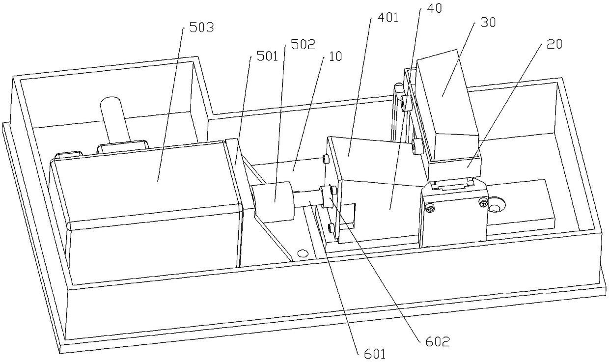
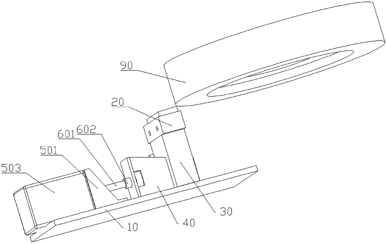
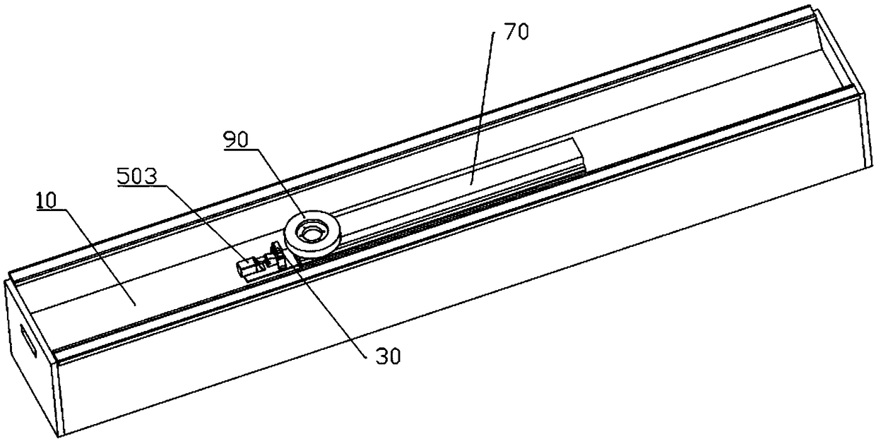
[0029] Embodiment 1 is basically as attached figure 1 , attached figure 2 And attached image 3 Shown: an automatic grinding device for grinding wheels, including a frame and a grinding mechanism, the frame includes a bottom plate 10 and a cage 20, and the cage 20 is fixed on the frame by bolts and nuts 602.

[0030] Such as figure 1 As shown, the grinding mechanism includes a trimming block 30, a top block 40, a reducer 501, a coupling 502, a screw 601, a nut 602 and a servo motor 503, the servo motor 503, a reducer 501, a coupling 502, a screw 601 and nut 602 are arranged in turn from left to right, the left end of the screw rod 601 is coaxially fixedly connected with the right end of the shaft coupling 502, the left end of the shaft coupling 502 is fixedly connected with the right end of the speed reducer 501, and the right end of the speed reducer 501 is connected with the servo The motors 503 are coaxially fixedly installed.

[0031] The trimming block 30 is in the s...

Embodiment 2

[0040] Embodiment 2 is basically as attached Figure 4 As shown, the difference between embodiment 2 and embodiment 1 is that a rubber sheet 402 is fixedly installed on the slope 401 of the trimming block 30, the rubber sheet 402 is in contact with the trimming block 30, and the bottom surface of the trimming block 30 is bonded to the rubber sheet 402, To facilitate the top block 40 when pushing the trimming block 30 to move up, the trimming block 30 is fed stably; as Figure 4 As shown, the upper end of the cage 20 is provided with a collection mechanism, the collection mechanism includes a bowl-shaped collection tank 801 and a number of brushes 802, the center of the collection tank 801 passes through the cage 20, and the collection tank 801 is buckled with the cage 20 Connected, the brush 802 is fixedly bonded on the upper surface of the collection tank 801 , and the brush 802 is in contact with the lower surface of the grinding wheel 90 .

[0041] When the lower surface o...


PUM


Abstract

The invention relates to relates to the field of sharpening technology and concretely discloses an automatic sharpening device for a grinding wheel. The device comprises a frame and a sharpening mechanism. The sharpening mechanism comprises a vertically-slipping reconditioning block, an ejection block used for ejecting the reconditioning block and an ejection rod driving the ejection block to horizontally move. The reconditioning block is vertically and slidably connected with the frame. One side of the reconditioning block contacts one side of the ejection block. One side, departing from theejection block, of the reconditioning block contacts the rotary grinding wheel. One side, close to the reconditioning block, of the ejection block is an oblique surface. According to the scheme, the position of the reconditioning block can be rapidly adjusted in order to rapidly recondition the grinding wheel.

Description

technical field [0001] The invention belongs to the technical field of grinding, and in particular relates to an automatic grinding device for grinding wheels. Background technique [0002] Knives need to be sharpened with a sharpener during the sharpening process, or sharpeners can be used to sharpen the edges of extremely blunt knives again. The knife grinder is a kind of special equipment that is driven by a special grinding head to drive the grinding wheel to grind the tool plane. The roughness and machining accuracy of the ground plane depend to a large extent on the sharpness and flatness of the grinding wheel used. The roughness and machining accuracy of the tool plane are closely related to the service life of the tool, and maintaining the sharpness and flatness of the grinding wheel during the grinding process is crucial to the service life of the tool. [0003] The existing grinding machine is generally equipped with a trimming block for grinding the grinding whee...

Claims


Application Information

Patent Timeline
IPC IPC(8): B24B53/06
CPCB24B53/06
Inventor 石剑刘勇胡惺
Owner 重庆派斯克刀具制造股份有限公司
Why Eureka
Try Eureka