Linear plasma gun head

A plasma and gun head technology, applied in the field of ion gun heads, can solve the problems of high processing, production and maintenance costs, uneven glass surface treatment, unstable operation, etc. Effect

Pending Publication Date: 2018-11-02
深圳市兴泰科技有限公司
View PDF0 Cites 0 Cited by
  • Summary
  • Abstract
  • Description
  • Claims
  • Application Information

AI Technical Summary

Problems solved by technology

However, when multiple plasma spray guns work at the same time, it is inevitable that superimposed treatment or missing treatment will occur, which will easily cause the problem of uneven glass surface treatment.

Method used


Image

  • Linear plasma gun head
  • Linear plasma gun head
  • Linear plasma gun head

Examples


Example Embodiment

[0061] Example 1

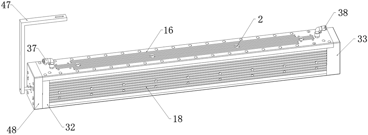
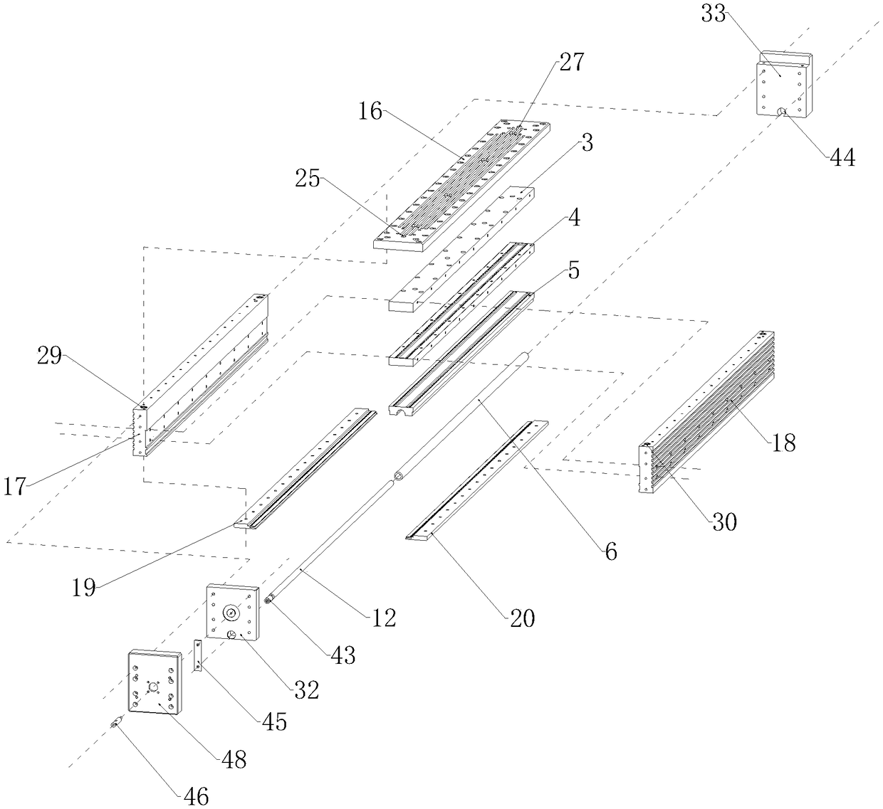
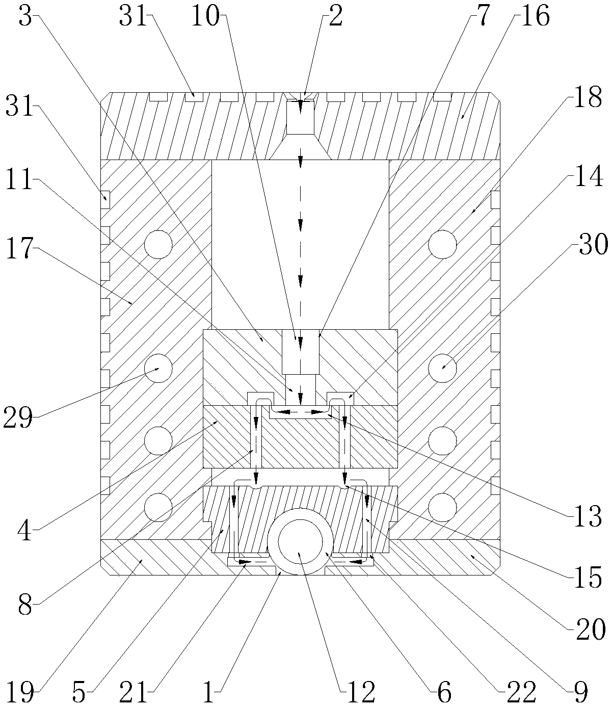
[0062] Such as Figure 1 to Figure 9 As shown, a linear plasma gun head includes a housing with a cavity, the bottom of the housing is provided with a strip outlet 1 communicating with the cavity, and the top of the housing is provided with an air inlet 2;

[0063] A first buffer plate 3, a second buffer plate 4, a third buffer plate 5, and a guide magnet tube 6 are arranged in the cavity of the housing from top to bottom. The guide magnet tube 6 is provided with an electrode 12 and the guide magnet tube 6 The bottom end is located at the strip-shaped outlet 1 and is provided with a gap between the strip-shaped outlet 1. The first buffer plate 3, the second buffer plate 4 and the third buffer plate 5, and the guide magnet tube 6 jointly divide the cavity into mutually independent first The buffer cavity, the second buffer cavity and the third buffer cavity. The bottom of the shell is provided with two fourth buffer cavities communicating with the strip outlet 1. ...

Example Embodiment

[0068] Example 2

[0069] This embodiment further defines the following on the basis of Embodiment 1: The first buffer plate 3 is spaced from the top of the cavity;

[0070] The first mixing hole 7 includes a large pore section 10 and a small pore section 11 located below the large pore section.

Example Embodiment

[0071] Example 3

[0072] This embodiment further defines the following on the basis of embodiment 1: the upper end surface of the second buffer plate 4 is arranged in contact with the lower end surface of the first buffer plate 3;

[0073] The top of the second buffer plate 4 is provided with a first buffer groove 13 facing the first mixing hole group, and the width of the first buffer groove 13 is larger than the diameter of the bottom end of the first mixing hole 7;

[0074] The bottom end of the first buffer plate 3 is provided with two second buffer grooves 14, the two second buffer grooves 14 are symmetrically arranged with respect to the first mixing hole group, and the second buffer groove 14 and the first buffer groove 13 and the The second mixing hole group is connected.


PUM


Abstract

The invention discloses a linear plasma gun head. The linear plasma gun head comprises a hollow rectangular cavity composed of a left side plate, a right side plate, an upper end plate, a left bottomplate, a right bottom plate and baffle plates. The upper end plate is equipped with a first air inlet, the first air inlet is connected to a second air inlet pipeline located on a first connecting plate, the lower end face of the first connecting plate is equipped with a first air inlet passage, the upper end face of the second connecting plate is provided with a ventilation groove, the second connecting plate is equipped with a third air inlet, the ventilation groove is connected to the third air inlet through the first air inlet passage, a gap is disposed between the second connecting plateand a third connecting plate, fourth air inlets are arranged on both sides of the third connecting plate, the bottom end of the third connecting plate is fixedly connected to the limit grooves locatedat the right end of the left bottom plate and the left end of the right bottom plate respectively, strip grooves are disposed at the lower ends of the limit grooves, a fifth air inlet is disposed below the fourth air inlet, and the lower end of the third connecting plate is equipped with a semi-circular groove and is connected to a guide magnetic pipe through the semi-circular groove.

Description

technical field [0001] The invention relates to the field of plasma technology, in particular to a linear plasma gun head. Background technique [0002] In the process of glass panel processing, most of the glass panel surfaces are coated, such as glass screens. In order to obtain a good coating effect, plasma treatment is usually performed on the glass panel before coating to improve surface activity and increase surface tension. Atmospheric pressure plasma machines are mostly used in the existing glass plasma treatment equipment, which can effectively plasma treat small-width glass panels through plasma spray guns. When the glass panel width is large, especially when it exceeds 80mm, it is necessary to install Multiple plasma torches are sufficient for the treatment. However, when multiple plasma spray guns work at the same time, superimposed treatment or missing treatment will inevitably occur, which will easily cause the problem of uneven glass surface treatment. In a...

Claims


Application Information

Patent Timeline
IPC IPC(8): C03C23/00
CPCC03C23/006
Inventor 王嘉伟洪秀谢详忠
Owner 深圳市兴泰科技有限公司
Why Eureka
Try Eureka