Milling machinery walking system based on four-wheel independent steering
A four-wheel independent steering and walking system technology, applied in roads, road repairs, roads, etc., can solve problems such as bulky, large-scale milling machinery with high complexity, and difficulty in achieving ideal steering conditions, and achieve precise steering effects
- Summary
- Abstract
- Description
- Claims
- Application Information
AI Technical Summary
Problems solved by technology
Method used
Image
Examples
Embodiment 1
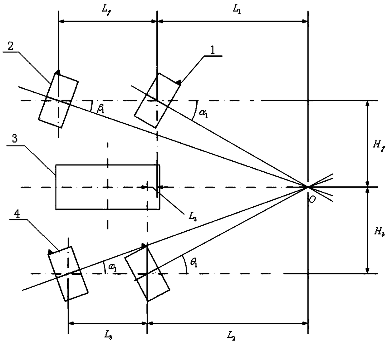
[0031] Such as figure 1 As shown, take the extension line of the center of the milling drum as the center of rotation. In the figure, the distance between the two front wheels in the x-coordinate direction is L f , the distance between the two rear wheels in the x-coordinate direction is L b , the distance between the front wheel center and the y-coordinate direction of the milling drum is H f , the distance between the rear wheel center and the y-coordinate direction of the milling drum is H b , the distance between the front and rear wheel centers in the x-coordinate direction is L 3 . Assuming turning to the right, the right front wheel 1 is the reference wheel, and the turning angle is α 1 , the intersection point of the extension line of the center of the right front wheel 1 and the milling drum 3 is the center O, and the turning angles of the other left front wheel 2, right rear wheel and left rear wheel 4 are deduced according to the Ackerman angle theorem as follo...
Embodiment 2
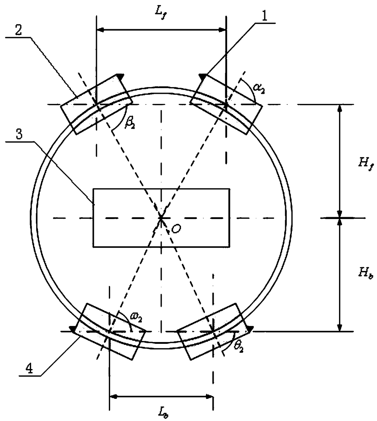
[0037] Such as figure 2 As shown, turn in situ. In the figure, the distance between the two front wheels in the x-coordinate direction is L f , the distance between the two rear wheels in the x-coordinate direction is L b , the distance between the front wheel center and the y-coordinate direction of the milling drum is H f , the distance between the rear wheel center and the y-coordinate direction of the milling drum is H b . When the in-situ steering is pressed, the in-situ steering is performed with the center of the milling drum as the origin. The centerlines of the four wheels are all tangent to the circle with O as the center. After calculation, the turning angle is as follows:
[0038]
[0039] beta 2 = α 2
[0040]
[0041] ω 2 = θ 2
[0042] After the controller inversely calculates the data of the steering of each wheel and outputs it to the steering cylinder to control the output angle.
Embodiment 3
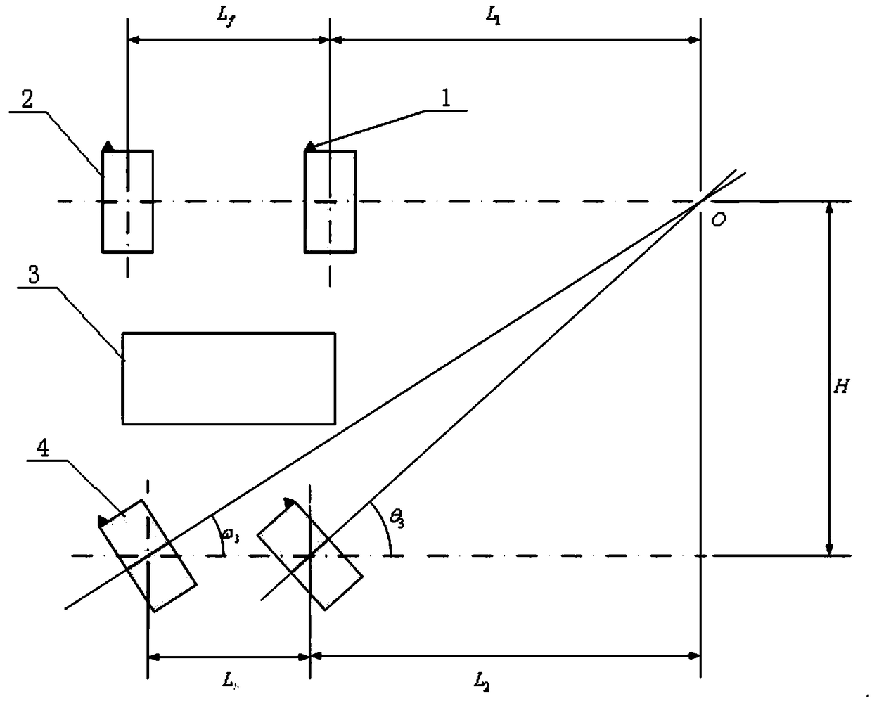
[0044] Such as image 3 As shown, the steering is centered on the center of the extension line of the front wheel center. In the figure, the distance between the two front wheels in the x-coordinate direction is L f , the distance between the two rear wheels in the x-coordinate direction is L b , the distance between the front wheel center and the y-coordinate direction of the milling drum is H f , the distance between the rear wheel center and the y-coordinate direction of the milling drum is H b , the front wheels move forward vertically. Assuming turning to the right, the right rear wheel is the reference wheel, and the turning angle is θ 3 , the intersection point of the extension lines of the center of the front wheel and the right rear wheel is the center O. According to the Ackerman angle theorem, the turning angle of the left rear wheel is deduced as follows:
[0045]
[0046] After the controller inversely calculates the data of the steering of each wheel and ...
PUM
 Abstract
Description
Claims
Application Information
 - R&D
- Intellectual Property
- Life Sciences
- Materials
- Tech Scout
- Unparalleled Data Quality
- Higher Quality Content
- 60% Fewer Hallucinations
Browse by: Latest US Patents, China's latest patents, Technical Efficacy Thesaurus, Application Domain, Technology Topic, Popular Technical Reports.
© 2025 PatSnap. All rights reserved.Legal|Privacy policy|Modern Slavery Act Transparency Statement|Sitemap|About US| Contact US: help@patsnap.com


