Display backplane

A display backplane and back film technology, applied in the direction of identification devices, instruments, etc., can solve problems such as poor reliability, affecting the bending success rate and product yield of flexible display devices, metal wire 021 wrinkles, etc., to reduce metal wrinkles or the risk of fracture, improve the mass production yield of products, and improve the effect of bending success rate

Active Publication Date: 2018-11-02
BOE TECH GRP CO LTD +1
View PDF8 Cites 20 Cited by
  • Summary
  • Abstract
  • Description
  • Claims
  • Application Information

AI Technical Summary

Problems solved by technology

[0003] At present, when the bending process is performed on the bending area of ​​the flexible display device, the bending resistance of the bending area is an important indicator of the flexible display device, such as figure 1 In the shown display backplane, the connection layer is Foam adhesive layer (polyurethane foam glue) 01 to support and bond the bent display backplane, and the non-bending area 03 of the display backplane includes SD (source-drain metal layer) and The back film 031 set on the SD032, the forming process of the existing bending area 02 includes two steps of pre-pressing and main pressing. When the main pressing head 04 moves downward, the connecting layer 01 and the pressure-sensitive adhesive coated The back film 031 contacts, because the edge of the connection layer 01 is close to the edge of the back film 031 of the non-bending area 03, the edge of the connection layer 01 (such as figure 2 Middle A position) will have a significant upward extrusion effect on the metal trace 021. Since the thickness of the back film is less than one-tenth of the thickness of the connection layer 01, the gradient area of ​​the back film 031 will appear on the non-bending area 03 Stress concentration area B, which in turn leads to wrinkling or breaking of the metal wire 021, causing poor reliability and device failure, resulting in poor contact of the circuit in the backplane, affecting the bending success rate and product yield of the flexible display device

Method used


Image

  • Display backplane
  • Display backplane
  • Display backplane

Examples


Embodiment Construction

[0028] The following will clearly and completely describe the technical solutions in the embodiments of the present invention with reference to the accompanying drawings in the embodiments of the present invention. Obviously, the described embodiments are only some, not all, embodiments of the present invention. Based on the embodiments of the present invention, all other embodiments obtained by persons of ordinary skill in the art without making creative efforts belong to the protection scope of the present invention.

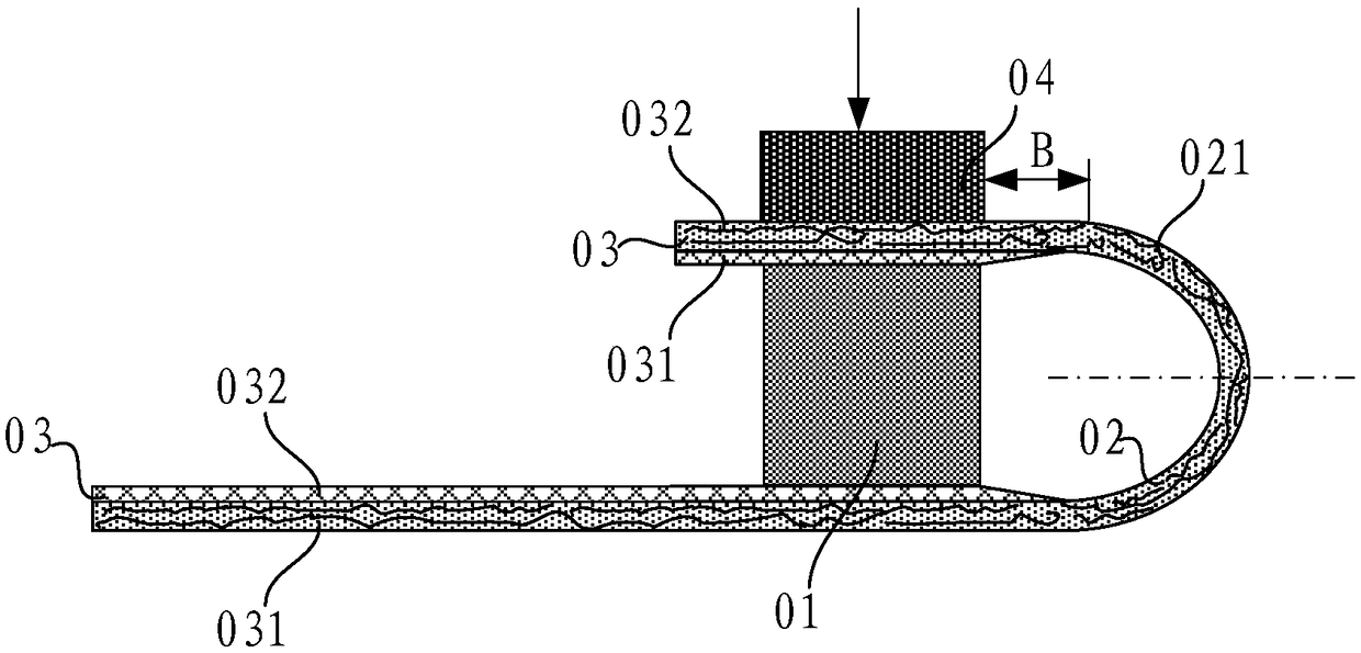
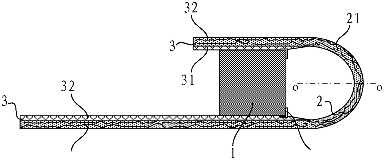
[0029] Such as image 3 , Figure 4 , Figure 5 , Image 6 , Figure 7 , Figure 8 as well as Figure 9 As shown, a display backplane includes a bending area 2, a non-bending area 3 and a connecting layer 1, the non-bending area 3 includes a first non-bending area and a second non-bending area, and the bending area 2 is connected to The first non-bending area and the second non-bending area, the connecting layer 1 is arranged between the first non-bendin...


PUM


Abstract

The invention relates to the technical field of display, and discloses a display backplane which comprises a bent region, non-bent regions and a connection layer. The non-bent regions include a firstnon-bent region and a second non-bent region, the first non-bent region and the second non-bent region are connected with each other by the bent region, the connection layer is arranged between the first non-bent region and the second non-bent region and is close to the bent region, and the first non-bent region and the second non-bent region can be supported by the connection layer and can be adhered with the connection layer. The display backplane has the advantages that cushion structures for cushioning squeezing effects of the edges of the connection layer on the non-bent regions are formed at the edges, which are close to the bent region, of the connection layer, cushion effects can be realized by the cushion structures when bending processes are carried out on the bent region of thedisplay backplane, accordingly, back films of the non-bent regions and metal in source and drain electrode metal layers of the non-bent regions can be prevented from being directly squeezed by the edges of the connection layer, squeezing acting force which is applied by the edges of the connection layer on metal routing in the bent region can be reduced, breakage of an internal metal wire can be reduced when the bent region is bent, the bending success rate of the display backplane can be increased, and the mass production yield of products can be increased.

Description

technical field [0001] The present invention relates to the field of display technology, in particular to a display backplane. Background technique [0002] With the advancement of display technology, flexible display devices have attracted more and more attention due to their advantages of low power consumption, small size, direct visual flexibility, deformability and bendability, and the development of flexible and bending-resistant display products has become a major issue in the display field. The focus of research, especially flexible OLED (organic light-emitting diode) display devices that can achieve narrow borders is a current research and development hotspot. [0003] At present, when the bending process is performed on the bending area of ​​the flexible display device, the bending resistance of the bending area is an important index of the flexible display device, such as figure 1 In the shown display backplane, the connection layer is Foam adhesive layer (polyure...

Claims


Application Information

Patent Timeline
Patent Type & Authority Applications(China)
IPC IPC(8): G09F9/30
CPCG09F9/301
Inventor 黄鹏詹志锋杨恕权王研鑫石佳凡王伟
Owner BOE TECH GRP CO LTD
Why Eureka
Try Eureka