Bouncing-prevention buffer mechanism of low-voltage switch

A low-voltage switch and buffer mechanism technology, applied in the contact drive mechanism, contact vibration/impact damping, etc., can solve the problems of poor stability of the anti-bounce device, and achieve the effects of convenient installation and maintenance, flexible rotation, and reduced maintenance costs.

Pending Publication Date: 2018-11-02
SHANGHAI LIANGXIN ELECTRICAL
View PDF1 Cites 0 Cited by
  • Summary
  • Abstract
  • Description
  • Claims
  • Application Information

AI Technical Summary

Problems solved by technology

[0005] The purpose of the present invention is aimed at the technical defect of the poor stability of the anti-bounce device of the above-mentioned existing low-voltage switch, and provides a kind of anti-bounce buffer mechanism of the low-voltage switch. Install the buffer to play the role of buffer force, and combine the anti-bounce device and the bracket into one, not only can fix the main shaft of the mechanism and rotate flexibly, but also can effectively restrain the cantilever of the switch main shaft from bouncing, the installation and maintenance are more convenient, and the maintenance is reduced cost

Method used


Image

  • Bouncing-prevention buffer mechanism of low-voltage switch
  • Bouncing-prevention buffer mechanism of low-voltage switch
  • Bouncing-prevention buffer mechanism of low-voltage switch

Examples


Embodiment 1

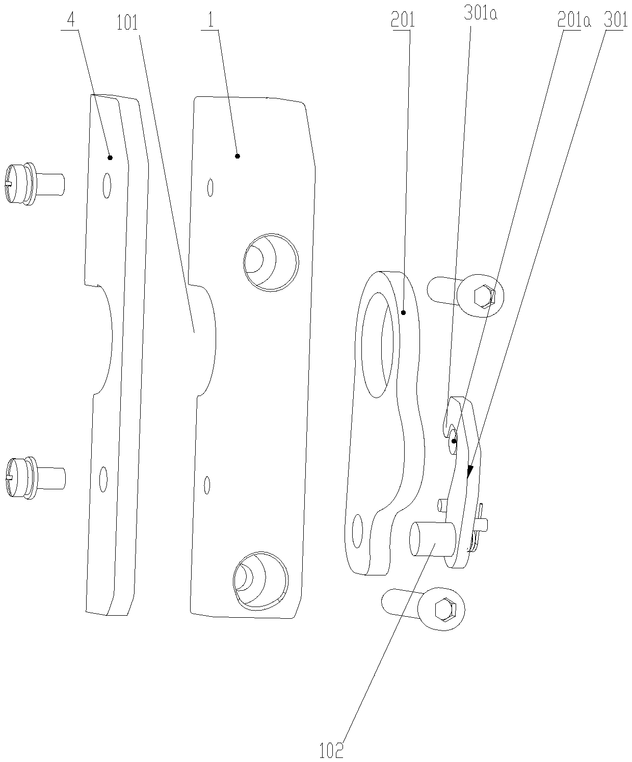
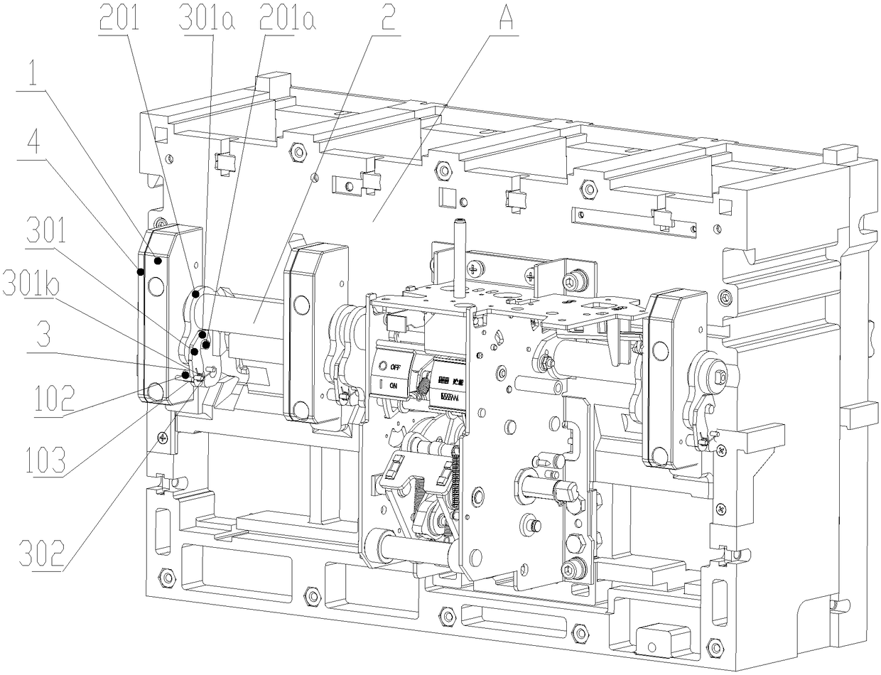
[0024] as attached figure 1 and 3 As shown, a low-voltage switch anti-bounce buffer mechanism, which includes a mechanism main shaft support 1, the upper and lower ends of the main shaft support 1 of the mechanism are mounted on the circuit breaker base A with screw locks, and the main shaft support 1 of the mechanism is provided with Half slot hole 101, the mechanism spindle 2 passes through the half slot hole 101 and is located in the space formed by the half slot hole 101 and the surface of the base A, wherein, the inner surface of the mechanism spindle support 1 is provided with an anti-bounce module 3 , the anti-bounce module 3 includes a resistance plate 301, the resistance plate 301 is installed on the support shaft 102 protruding from the inner side of the main shaft support 1 of the mechanism, the resistance plate 301 is provided with a clamping hook 301a, the A protrusion 301b is provided on the outer surface of the resistance plate 301 , and a torsion spring 302 is...

Embodiment 2

[0030] as attached Figure 5 , as shown in 6 and 8, the present invention also provides an embodiment that on the basis of embodiment 1, the inner surface of the main shaft support 1 of the mechanism is also equipped with an elastic buffer part 2 5, and the cantilever 201 of the main shaft 2 of the mechanism A stop rod 201b is provided.

[0031] as attached Figure 7 As shown, when the circuit breaker is opened, the stop rod 201b is in contact with the surface of the elastic buffer member 25 to absorb excess energy generated during the opening process and form resistance, thereby effectively reducing bouncing.

[0032] The invention provides an anti-bounce buffer mechanism for a low-voltage switch. An anti-bounce module is installed on the side of the bracket of the cantilever of the main shaft of the fixing mechanism. The buffer is installed on the bracket to play the role of buffer force, and the anti-bounce device and the bracket are combined into one. , not only can fix ...


PUM


Abstract

The invention relates to a bouncing-prevention buffer mechanism of a low-voltage switch. The bouncing-prevention buffer mechanism comprises a mechanism main shaft support (1), wherein a half-groove hole (101) is formed in the mechanism main shaft support (1), the bouncing-prevention buffer mechanism is characterized in that a bouncing-prevention module (3) is arranged on an inner side surface of the mechanism main shaft support (1) and comprises a resistance plate (301), the resistance plate (301) is arranged on a fulcrum shaft (102), the fulcrum shaft (102) extends out of the inner side surface of the mechanism main shaft support (1), and a clamping hook (301a) is arranged on the resistance plate (301) and can be used for clamping a strut (201a) extending out of an outer side surface of an upper cantilever (201) of a mechanism main shaft (2) during breaking. In the bouncing-prevention buffer mechanism, the bouncing-prevention module is arranged on a side surface of a support of a mainshaft cantilever of a fixed mechanism, a buffer piece is arranged on the support and have an effect of a buffer force, the bouncing-prevention device and the support are combined, the mechanism mainshaft can be fixed and flexibly rotate, the cantilever of a switch main shaft also can be effectively prevented from bouncing, the bouncing-prevention buffer mechanism is relatively convenient to install and maintain, and the maintenance cost is reduced.

Description

technical field [0001] The invention belongs to the technical field of low-voltage switches, and in particular relates to an anti-bounce buffer mechanism for low-voltage switches. Background technique [0002] During the closing operation of the switch, the cantilever main shaft links the moving contact to make the moving contact rotate in the direction of the switch bottom plate. During this process, the reaction spring of the operating mechanism itself is stretched, and the spring force of the reaction spring is overcome. ; There is a contact spring on the moving contact. After the switch completes the closing operation, the contact spring is compressed to provide the contact pressure when the switch is closed. [0003] When the switch is opened, under the reaction force of the reaction spring tension of the operating mechanism and the spring pressure of the moving contact, the cantilever main shaft of the operating mechanism rotates rapidly, and the moving contact rotates...

Claims


Application Information

Patent Timeline
IPC IPC(8): H01H3/60H01H3/32
CPCH01H3/32H01H3/60
Inventor 何春张海灵尹家灿
Owner SHANGHAI LIANGXIN ELECTRICAL
Why Eureka
Try Eureka