Large channel bending portion of endoscope insertion tube

A technology of inserting a tube and a large channel, applied in the field of endoscopy, can solve the problems of reducing the effective inner diameter of the snake bone, difficulty in enlarging the working channel, and reducing the space utilization rate of the snake bone.

Pending Publication Date: 2018-11-06
ZHUHAI VISION MEDICAL TECH CO LTD
View PDF7 Cites 1 Cited by
  • Summary
  • Abstract
  • Description
  • Claims
  • Application Information

AI Technical Summary

Problems solved by technology

[0002] At present, the bending part of endoscope flexible mirror is realized by snake bone (Bending Section). There are traction holes or traction grooves on both sides or four sides of the snake bone, and the steel wire passes through to realize the bending angle. The current snake bone outer surface It is generally circular, and the effective inner diameter of the snake bone is greatly reduced after the traction hole or traction groove is recessed inward, which makes it difficult to enlarge the critical working channel in the endoscope soft mirror. The working channel is mainly for supplying The passage of tools such as instruments determines the size of the tool, thus limiting the size and type of tools that can pass through the working channel, and due to the existence of traction holes or traction grooves, the space utilization rate in the snake bone is also greatly reduced

Method used


Image

  • Large channel bending portion of endoscope insertion tube
  • Large channel bending portion of endoscope insertion tube
  • Large channel bending portion of endoscope insertion tube

Examples


Embodiment Construction

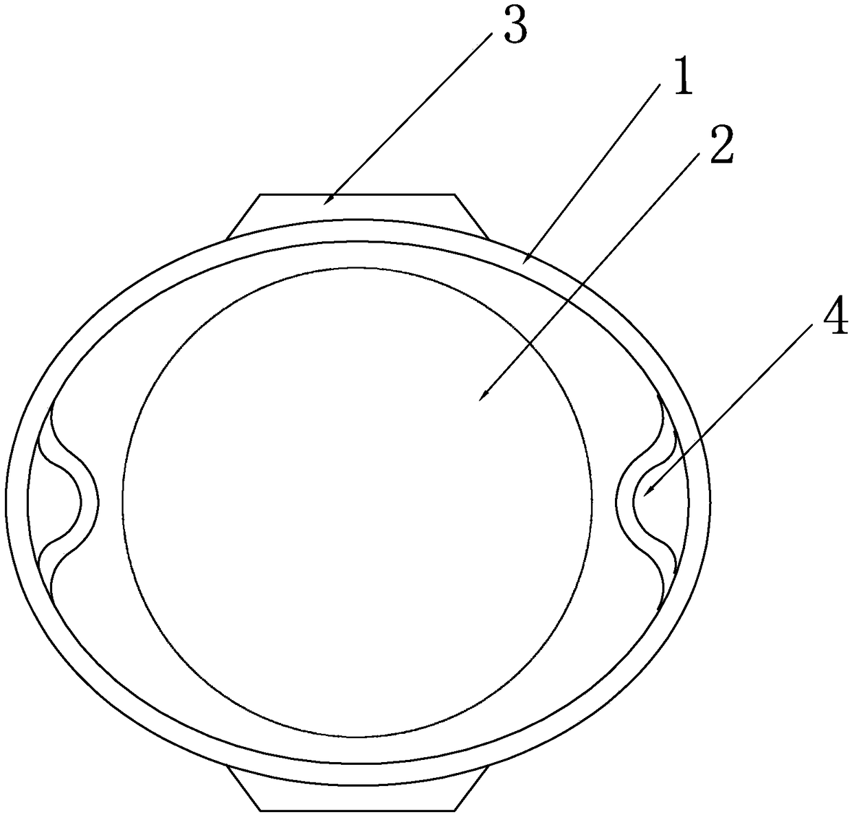
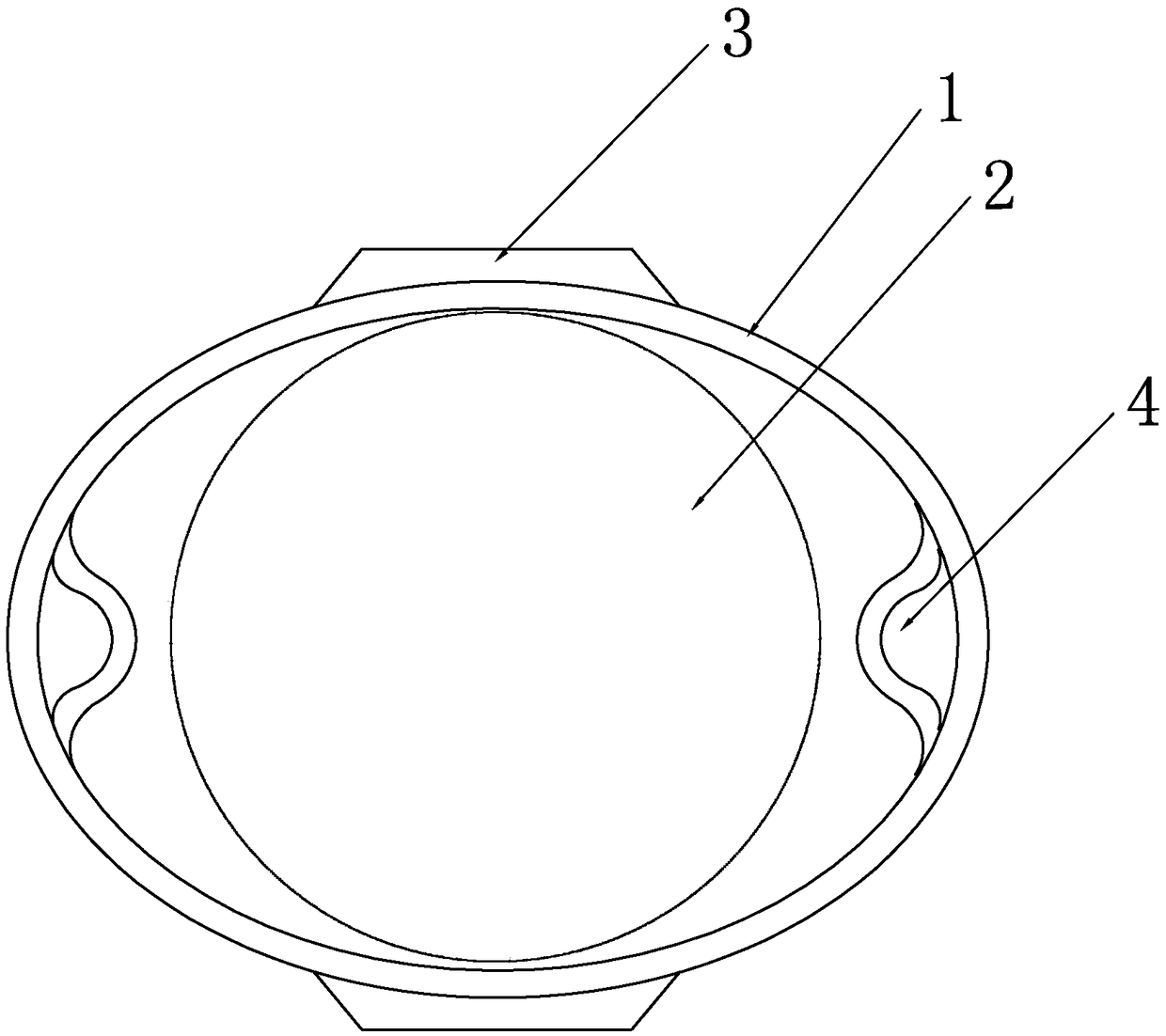
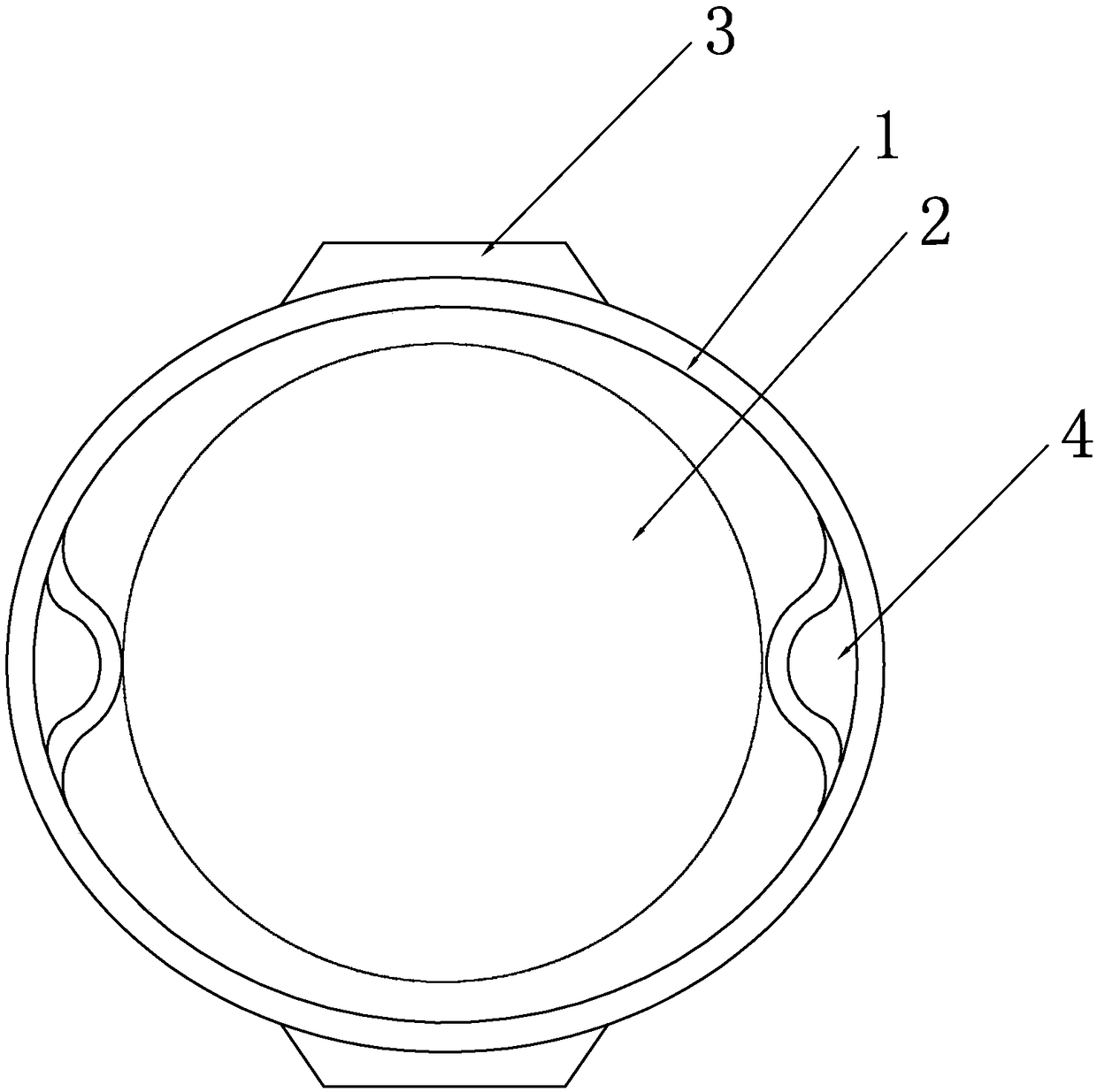
[0019] see figure 1 , a large channel bending portion of an endoscope insertion tube of the present invention includes a snake bone joint tube 1 and a working channel 2 disposed in the snake bone joint tube 1, and the snake bone joint tube 1 includes a plurality of sequentially hinged Snake bone joints, the inner two ends of each snake bone joint are provided with traction holes or traction grooves for the traction wire to pass through. This embodiment is the traction hole 4. Oval, the traction holes are arranged at both ends of the major axis of the cross section of the snake joint tube 1, and the cross section of the working channel 2 is circular.

[0020] Wherein, two adjacent snake bone joints are hinged together by a hinge 3, and the hinge 3 is located outside the snake bone joint, and two adjacent snake bone joints are hinged together by two hinges 3, the two The two hinge parts 3 are respectively located at the two ends of the extension line of the minor axis of the cr...


PUM


Abstract

The invention discloses a large channel bending portion of an endoscope insertion tube. The portion comprises a snake bone joint tube and a working channel disposed in the snake bone joint tube, the snake bone joint tube comprises a plurality of snake bone joints hinged in sequence, traction holes or traction grooves through which traction wires passe are formed in two ends of the inner side of each snake bone joint, the cross section of the outer curved surface of the snake bone joint tube is elliptical, the traction holes or the traction grooves are formed in both ends of the long axis of the cross section of the snake bone joint tube, and the cross section of a working channel is circular. The bending portion is ingenious and reasonable in design, the cross section of the outer curved surface of the snake bone joint tube is designed to be elliptical, the traction holes or the traction grooves are formed in both ends of the long axis of the cross section of the snake bone joint tube,the cross section of the working channel is circular, in the case of the same cross section area of the snake bone joint tube, the effective inner diameter of the inner portion of a snake bone is increased, the working channel is expanded, and greater possibilities are provided for sizes and types of tools passing through the working channel.

Description

technical field [0001] The invention relates to the technical field of endoscopes, in particular to a large channel bending part of an endoscope insertion tube. Background technique [0002] At present, the bending part of endoscope flexible mirror is realized by snake bone (Bending Section). There are traction holes or traction grooves on both sides or four sides of the snake bone, and the steel wire passes through to realize the bending angle. The current snake bone outer surface It is generally circular, and the effective inner diameter of the snake bone is greatly reduced after the traction hole or traction groove is recessed inward, which makes it difficult to enlarge the critical working channel in the endoscope soft mirror. The working channel is mainly for supplying The passage of tools such as instruments determines the size of the tool, thus limiting the size and type of tools that can pass through the working channel, and due to the existence of traction holes or ...

Claims


Application Information

Patent Timeline
Patent Type & Authority Applications(China)
IPC IPC(8): A61B1/005
CPCA61B1/0055
Inventor 李天宝刘玺诚杨凯田绍林
Owner ZHUHAI VISION MEDICAL TECH CO LTD
Why Eureka
Try Eureka