Reciprocating spraying machine with two arms and six shafts

A spraying machine and six-axis technology, applied in the direction of spraying device, can solve the problems of large blind area of ​​spraying, poor quality of sprayed products, and inability to spray products, and achieve the effect of high coating transfer efficiency, good product quality and low design cost.

Pending Publication Date: 2018-11-06
东莞市睿晶自动化设备有限公司
View PDF0 Cites 15 Cited by
  • Summary
  • Abstract
  • Description
  • Claims
  • Application Information

AI Technical Summary

Problems solved by technology

[0003] In order to achieve the spraying of plastic products with different appearance structures in the existing industry, a variety of special spraying machines have been designed in the existing ones, but the shortcomings of the existing spraying machines for high-demand spraying such as automotive interior parts are: First, when the existing spraying machine sprays, the product cannot be sprayed in all directions, and the spraying blind area is large; second, the existing spraying machine has low spraying efficiency and the quality of the sprayed product is poor; third, the existing spraying machine is automated. Low and high design cost

Method used


Image

  • Reciprocating spraying machine with two arms and six shafts
  • Reciprocating spraying machine with two arms and six shafts
  • Reciprocating spraying machine with two arms and six shafts

Examples


Embodiment Construction

[0025] The present invention will be described in further detail below in conjunction with the accompanying drawings.

[0026]The embodiments described by referring to the figures are exemplary and are intended to explain the present application and should not be construed as limiting the present application. In the description of the present application, it should be understood that the terms "center", "longitudinal", "transverse", "length", "width", "thickness", "upper", "lower", "front", " Orientation or position indicated by "back", "left", "right", "vertical", "horizontal", "top", "bottom", "inner", "outer", "clockwise", "counterclockwise", etc. The relationship is based on the orientation or positional relationship shown in the drawings, and is only for the convenience of describing the present application and simplifying the description, rather than indicating or implying that the referred device or element must have a specific orientation, be constructed and operated i...


PUM


Abstract

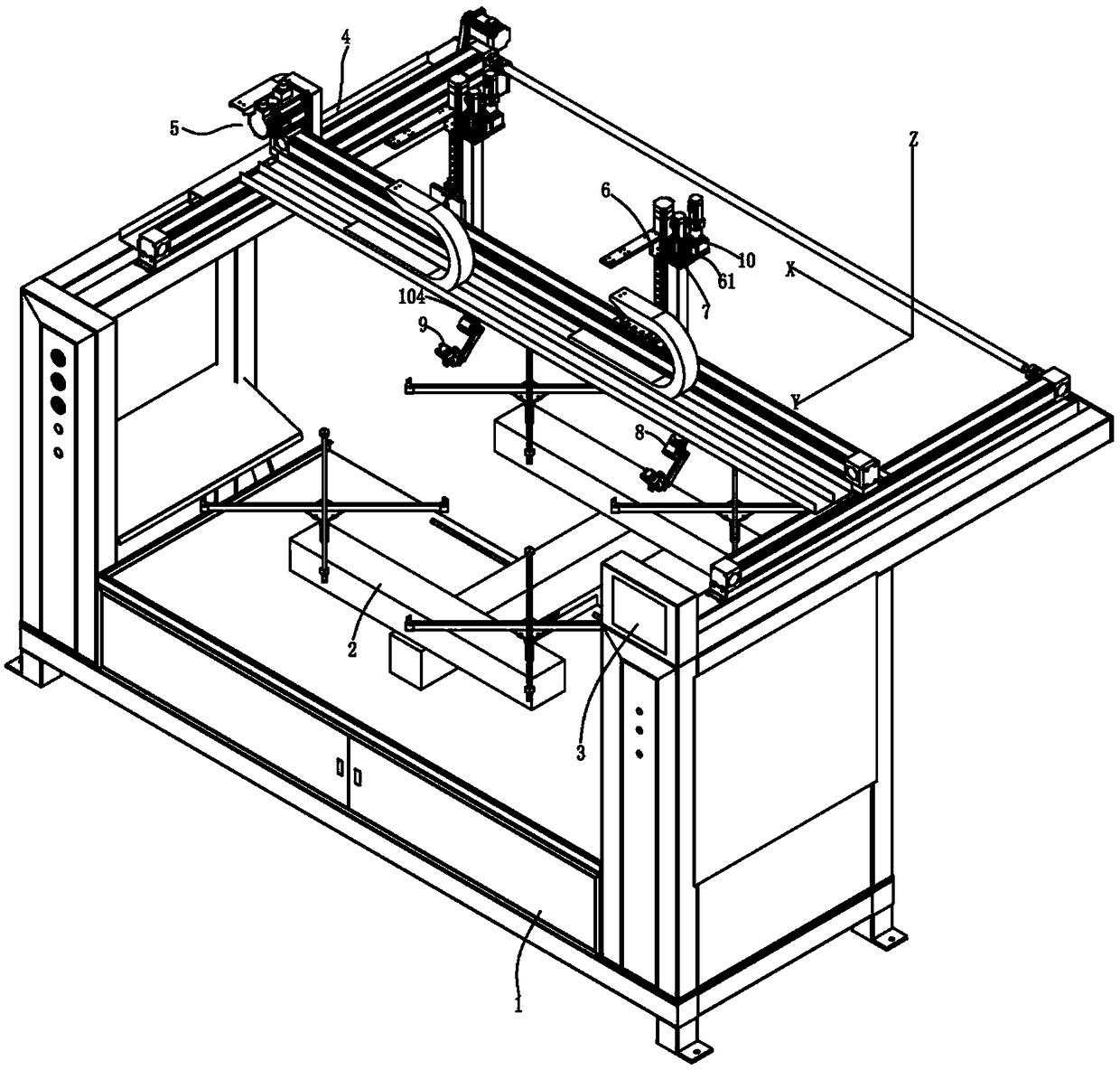
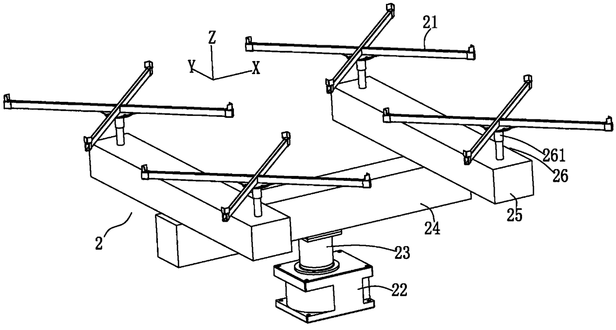
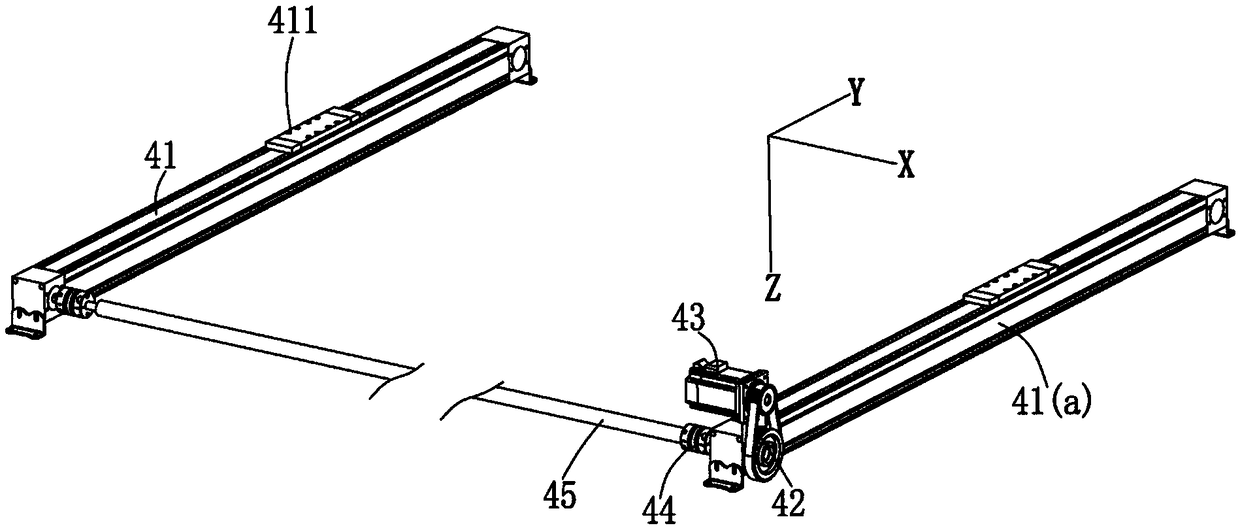
The invention discloses a reciprocating spraying machine with two arms and six shafts. The reciprocating spraying machine comprises a rotary feeding assembly arranged on a rack. The rotary feeding assembly is provided with tray clamps capable of rotating. The tray clamps can be driven by the rotary feeding assembly to rotate, and a workpiece can be driven to rotate between a spraying position anda blanking position. Two Y-direction transmission assemblies are also arranged at the upper end of the rack. An X-direction transmission assembly is arranged on the two Y-direction assemblies in a crossing manner. One or more Z-direction transmission assemblies are arranged on the X-direction transmission assembly in a hung manner. A mounting base plate is arranged at the upper end of each Z-direction transmission assembly. Each mounting base plate is provided with an R-shaft transmission assembly. A rotary swinging assembly is in transmission connection with and arranged at the bottom end ofthe transmission shaft of each R-shaft transmission assembly. Each rotary swinging assembly is connected with a spray gun assembly. Each spray gun assembly is driven to swing by each R-shaft transmission assembly through each rotary swinging assembly. A rotary shaft is arranged on the transmission shaft of each R-shaft transmission assembly in a sleeving manner, wherein each rotary shaft and the transmission shaft of each R-shaft transmission assembly are coaxially arranged. Each rotary shaft is connected with a driving device through a synchronous belt drive pair and connected with each rotary swinging assembly through a linear bearing. Each rotary shaft is driven to rotate by each driving device, and each rotary swinging assembly and spray gun assembly can be driven to rotate by each driving device.

Description

technical field [0001] The invention relates to the technical field of automatic spraying equipment, in particular to a double-arm six-axis reciprocating spraying machine. Background technique [0002] Spraying machine is a kind of equipment that sprays paint into fine mist droplets by compressed air and sprays it on the surface of workpiece under the drive of airflow. It can provide objects with functions such as beauty and surface protection. With the development of science and technology, various waterproof coatings, Anti-oxidation coatings and wear-resistant coatings emerge in endlessly, which also put forward higher requirements for spraying machines. [0003] In order to achieve the spraying of existing plastic products with different appearance structures, a variety of special spraying machines have been designed, but the existing spraying machines for high-demand spraying of automotive interior parts have the following shortcomings: First, when the existing spraying...

Claims


Application Information

Patent Timeline
Patent Type & Authority Applications(China)
IPC IPC(8): B05B13/04B05B15/68B05B13/02
CPCB05B13/0431B05B13/0228B05B13/025B05B13/0405B05B13/0421B05B15/68
Inventor 冯奕成
Owner 东莞市睿晶自动化设备有限公司
Why Eureka
Try Eureka