
A waste material collection device on a cutting machine for processing transmitter casings

A waste collection and cutting machine technology, which is applied to metal processing machinery parts, metal processing equipment, manufacturing tools, etc., can solve problems such as danger, inconvenience, and troublesome unloading of waste, and achieve improved safety and high friction Effect

Active Publication Date: 2020-06-09
浙江联品电子科技有限公司
View PDF17 Cites 0 Cited by
  • Summary
  • Abstract
  • Description
  • Claims
  • Application Information

AI Technical Summary

Problems solved by technology

[0003] In the recycling device of the prior art, when reclaiming waste steel strips, the waste is often wound on one place on the winding rod and is very firm, so it is very inconvenient to remove the waste from the winding rod. It is very troublesome to unload the waste. If you want the waste to be evenly distributed on the winding rod, you need to guide it manually, which is dangerous

Method used


Image

  • A waste material collection device on a cutting machine for processing transmitter casings
  • A waste material collection device on a cutting machine for processing transmitter casings
  • A waste material collection device on a cutting machine for processing transmitter casings

Examples


Embodiment Construction

[0026] The following are specific embodiments of the present invention and the technical solution of the present invention will be further described in conjunction with the accompanying drawings.

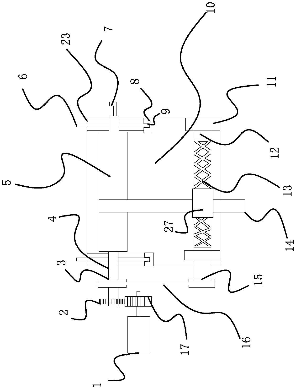
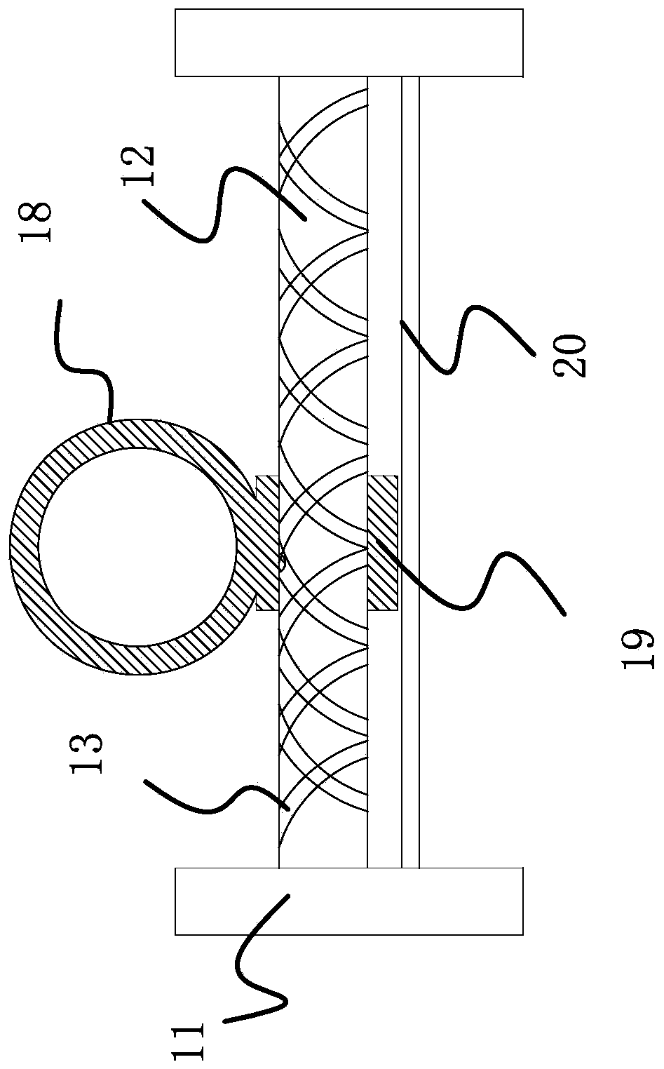
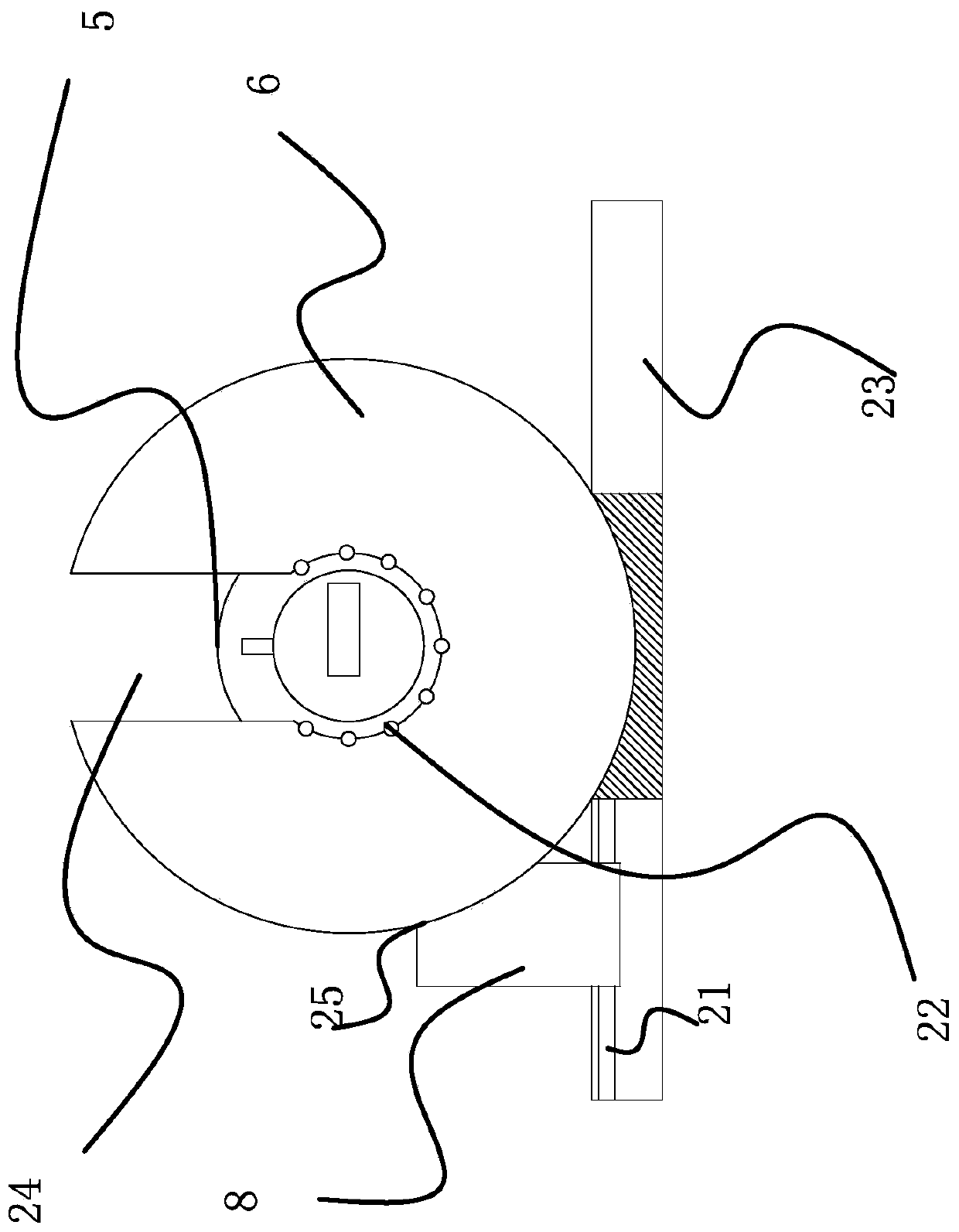
[0027] like figure 1 , figure 2 , image 3 and Figure 4 Shown, a kind of waste collection device on the cutting machine of processing transmitter chassis, it comprises machine base 10, winding mechanism, guide mechanism and transmission mechanism, it is characterized in that, described guide mechanism is arranged on the front of winding mechanism and Both are arranged on the machine base 10, and the transmission mechanism is connected between the guide mechanism and the winding mechanism. The winding device includes a winding rod 4 with a driven gear 2 at the end, and a winding rod 4 sleeved on the winding rod 4. The disc 6, the support seat 23 for placing the disc 6 with semicircular grooves on the surface and the block 8 slidingly connected to the support seat 23, the center ...


PUM


Abstract

The invention provides a waste collection device of a shearing machine used for machining a transmitter case. A guide mechanism is arranged in front of a winding mechanism, and both the guide mechanism and the winding mechanism are arranged on a machine base. A winding device comprises a winding rod, a disc, a supporting base and a clamping block, wherein a driven gear is arranged at the end of the winding rod; the winding rod is sleeved with the disc; a semicircular groove is formed in the surface of the supporting base, and the disc is placed on the supporting base; and the clamping block isslidably connected to the supporting base. The guide mechanism comprises a rotary shaft, baffles, a sliding base and a supporting plate, wherein a double-spiral groove is formed in the surface of therotary shaft; the baffles are rotatably connected to the two sides of the rotary shaft; the sliding base is slidably connected to the rotary shaft; the supporting plate supports the sliding base, andthe surface of the supporting plate is attached to the bottom of the sliding base. The upper half portion of the sliding base is an annular block, the lower half portion of the sliding base is a square block, a through hole is formed in the middle of the square block, and a lug embedded into the double-spiral groove is arranged in the through hole. When the rotary shaft rotates, the lug slides along the double-spiral groove to enable the sliding base to move leftwards or rightwards back and forth. According to the waste collection device, waste is guided through the sliding base, the slidingbase moves back and forth along the rotary shaft to guide waste to be evenly wound on the winding rod, and manual guiding is not needed, so that the safety is improved, and using is very convenient.

Description

technical field [0001] The invention belongs to the technical field of machinery, and relates to a waste material collecting device on a cutting machine for processing transmitter casings. Background technique [0002] Due to the different size requirements of customers for steel strips, some large-sized steel strips need to be cut, and scraps often appear during the cutting process. These scraps are generally left at will, making it easy to cause safety hazards during the cutting process of steel strips. Usually Under normal circumstances, these waste materials are directly thrown to the two sides of the cutting equipment, and are piled up on both sides of the cutting equipment in a disorderly manner, and special personnel are required to regularly clean up the waste materials, which is not only time-consuming and laborious, but also makes it difficult to recycle the waste materials. In order to overcome the above-mentioned defects, a recovery device for steel strip cutting...

Claims


Application Information

Patent Timeline
Patent Type & Authority Patents(China)
IPC IPC(8): B23Q11/00
CPCB23Q11/0042
Inventor 王永森张思林周松
Owner 浙江联品电子科技有限公司
Learn More