Positioning and mounting fixture of photoelectric equipment

A technology for positioning installation and photoelectric equipment, applied in the direction of manufacturing tools, workpiece clamping devices, etc., can solve the problems of inability to disassemble, gaps in equipment, inability to use flexibly, etc., and meet the requirements of easy installation and high-precision installation Effect

Inactive Publication Date: 2018-11-06
WUHU CHUNYUAN PHOTOELECTRIC EQUIP TECH CO LTD
View PDF6 Cites 1 Cited by
  • Summary
  • Abstract
  • Description
  • Claims
  • Application Information

AI Technical Summary

Problems solved by technology

[0003] However, the existing installation fixtures have the following defects: during the installation process of the photoelectric device, due to the inaccurate initial positioning, there will be gaps between the devices or the problem that they cannot be installed during the installation process, and the existing fixtures are used. The integrated structure cannot be disassembled, and it cannot be used flexibly when facing equipment installations of different sizes

Method used


Image

  • Positioning and mounting fixture of photoelectric equipment
  • Positioning and mounting fixture of photoelectric equipment

Examples


Embodiment Construction

[0016] The technical solutions in the embodiments of the present invention will be clearly and completely described below in conjunction with the accompanying drawings in the embodiments of the present invention. Obviously, the described embodiments are only a part of the embodiments of the present invention, rather than all the embodiments. Based on the embodiments of the present invention, all other embodiments obtained by those of ordinary skill in the art without creative work shall fall within the protection scope of the present invention.

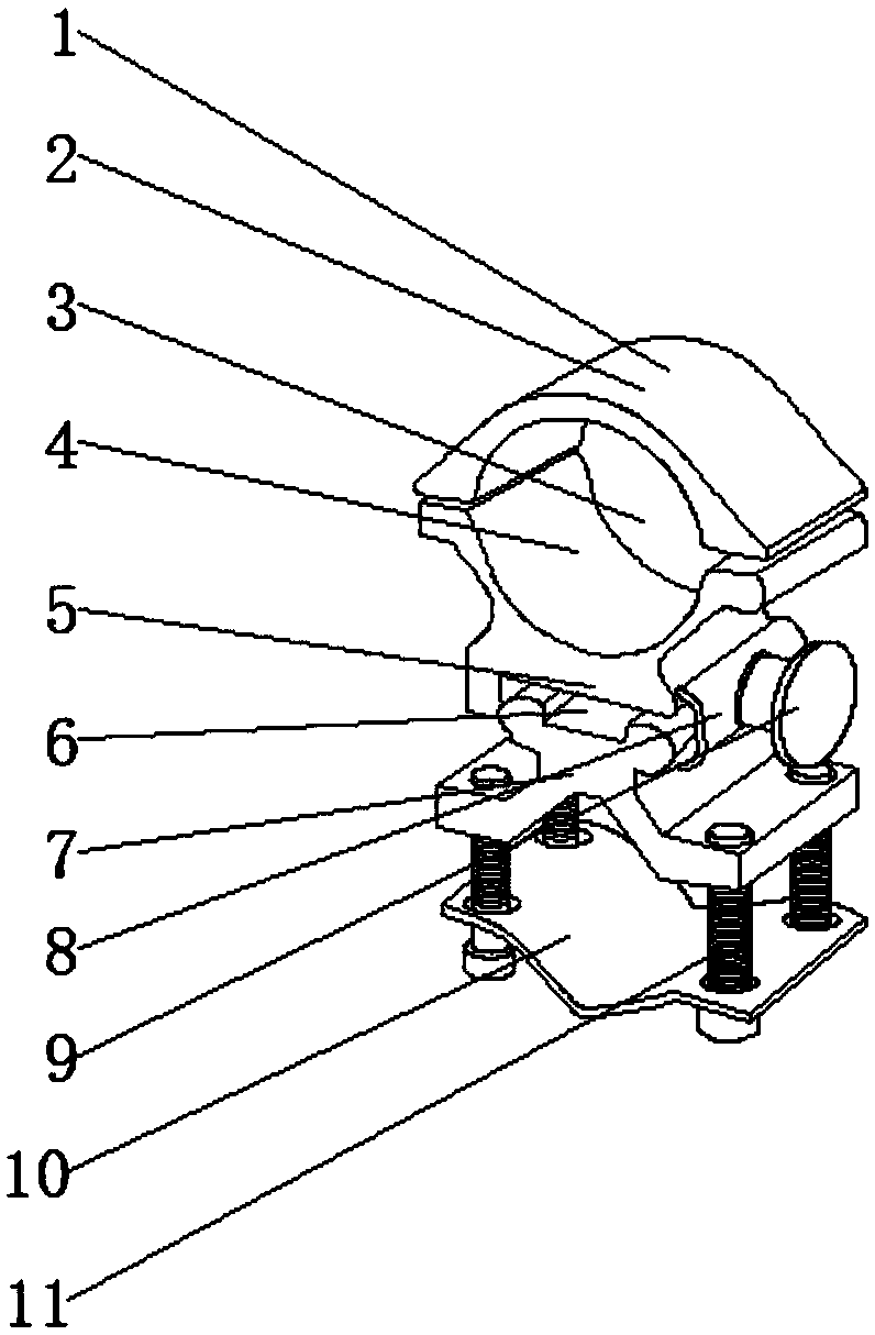
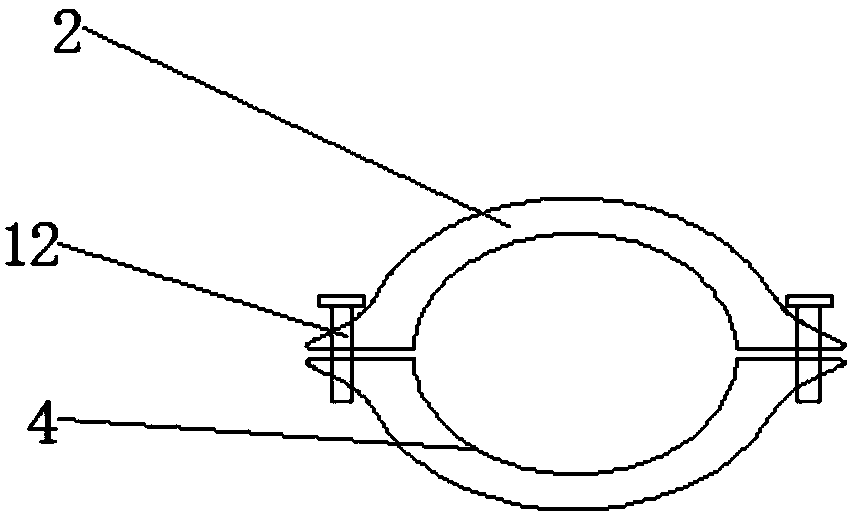
[0017] See Figure 1-2 , The present invention provides a technical solution: a positioning and installation fixture for optoelectronic equipment, including a mounting fixture 1 and a butterfly chuck 7, the top of the mounting fixture 1 is provided with a tubular upper clip 2, and the upper part of the mounting fixture 1 And the lower part of the upper clip 2 of the tube is provided with a lower tube holder 4, the upper clip 2 of the tub...


PUM


Abstract

The invention discloses a positioning and mounting fixture of photoelectric equipment. The positioning and mounting fixture of photoelectric equipment includes a mounting fixture and a butterfly chucks; a pipe-like upper clamping sheet is arranged at the top of the mounting fixture, a pipe-like lower clamping seat is arranged at the position, located on the lower portion of the pipe-like upper clamping sheet and on the upper portion of the mounting fixture, and the pipe-like upper clamping sheet is connected with the pipe-like lower clamping seat in a threaded mode through small screws; a clamping groove is formed in the lower portion of the pipe-like lower clamping seat, the butterfly chuck is arranged at the position, located on the lower portion of the pipe-like lower clamping seat andin the middle of the mounting fixture, and the pipe-like upper clamping sheet and a pipe-like lower clamping seat are arranged at the top of the mounting fixture; and the pipe-like upper clamping sheet is connected with the pipe-like lower clamping seat in a threaded mode through the small screws on the two sides, the size of an ellipse groove can be controlled by the small screws flexibly, a clamping groove is formed in the pipe-like lower clamping seat, the upper part of the butterfly chuck is placed in the clamping groove, the butterfly chuck is movably connected with the pipe-like lower clamping seat through fastening screws and gaskets, and the number of the clamping opening of the mounting fixture can be increased when needed.

Description

Technical field [0001] The present invention relates to the technical field of installation clamps, in particular to a positioning installation clamp for photoelectric equipment. Background technique [0002] Fixture is a device used to fix the processing object during the mechanical manufacturing process so that it occupies the correct position to accept construction or inspection. According to the different types of test pieces to be tested (plastic, metal, etc.) and different types of test methods (tensile, compression), it is necessary to replace the jigs for testing. Fixtures are also called fixtures. In a broad sense, in any process in the process, devices used to quickly, conveniently and safely install workpieces can be called fixtures. For example, welding fixtures, inspection fixtures, assembly fixtures, machine tool fixtures, etc. Among them, machine tool fixtures are the most common, often referred to as fixtures. [0003] However, the existing installation fixtures ...

Claims


Application Information

Patent Timeline
Patent Type & Authority Applications(China)
IPC IPC(8): B25B11/02
CPCB25B11/02
Inventor 梅霖
Owner WUHU CHUNYUAN PHOTOELECTRIC EQUIP TECH CO LTD
Why Eureka
Try Eureka