Laser paver and elevation setting method thereof

A technology of paver and laser marking instrument, which is applied to roads, road repairs, roads, etc., to achieve an intuitive effect of the elevation operation method

Pending Publication Date: 2018-11-06
莱赛激光科技股份有限公司
View PDF7 Cites 7 Cited by
  • Summary
  • Abstract
  • Description
  • Claims
  • Application Information

AI Technical Summary

Problems solved by technology

[0010] The technical problem to be solved by the present invention is a laser paver and its elevation setting method. Only one person can operate the elevation setting process of the laser paver according to the present invention. The elevation setting is accurate and the method is simple. There is no need to manually pave the datum plane before setting the level

Method used


Image

  • Laser paver and elevation setting method thereof
  • Laser paver and elevation setting method thereof
  • Laser paver and elevation setting method thereof

Examples


Embodiment 2

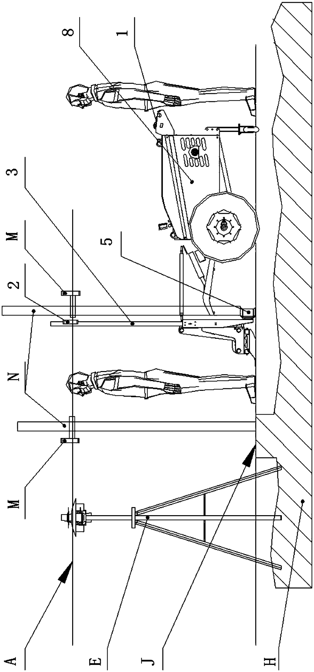
[0045] like Figure 4 , the elevation setting method of the laser paver described in the above-mentioned embodiment 1, comprising the following steps:

[0046] Step 1. Place the laser paver near the 50 line D. The 50 line D refers to the 50 line of the building. It is determined as ±0.000 on the floor surface of each floor, and ±0.000 is a reference plane of the main project. 0.000 is the benchmark and the line that is 50 cm upwards with the ink fountain on the wall W is the 50 line D. The starting surface used for the 50 line D is the reference level when paving the pavement materials. If there is no 50 line D on the construction site , can manually draw 50 lines D on any immovable object based on ±0.000; the 50 lines D can also be 60 lines, 80 lines, or 1 meter lines, because 50 lines are usually reserved on the wall W of the engineering site line, so this embodiment is preferably 50 lines; open the laser marking instrument 9 on the paver, and the laser surface B emitted by...

Embodiment 3

[0052] A working method of a laser paver, comprising the method for setting the elevation of the laser paver described in the above embodiment 2, further comprising the following steps:

[0053] During the laying process of the laser paver, when the body of the laser paver is disturbed and a receiver 2 is not at the height of the laser plane emitted by the laser sweeper E, the receiver transmits a signal to the laser paver The automatic controller of the machine, the automatic controller automatically controls the laser paver to adjust the scraper, so that the receiver returns to the height of the laser plane, and the bottom surface of the scraper returns to the reference plane.

[0054] The automatic controller adopts a single-chip microcomputer or PLC, etc.; the laser paver action drive mechanism is a drive mechanism for controlling the action of each part of the laser paver in the prior art, and it can be realized by a hydraulic system or a motor drive system.

[0055] The ...


PUM


Abstract

The invention relates to a laser paver which comprises a vehicle body and a laser line marking instrument and further comprises small push rods, wherein the small push rods are arranged at the left end and the right end of the front part of the vehicle body, scraper blades are fixed to the lower parts of the small push rods, transition connection parts are fixed to the left ends and the right endsof the scraper blades, the laser line marking instrument is arranged on the rear sides of the transition connection parts, vertical rods are fixed to the upper parts of all the transition connectionparts, height-adjustable receivers are arranged on all the vertical rods, and the laser line marking instrument can emit out a laser face parallel to a horizontal plane to present a horizontal laser line on a target article projected by the laser face. The laser paver disclosed by the invention can be operated by only one user in an elevation setting process, elevation setting is accurate, an elevation setting method is simple and convenient, and manually paving a baseplane before elevation setting is avoided.

Description

technical field [0001] The invention relates to a paver for road surfaces, in particular to a laser paver and a method for setting the elevation thereof. Background technique [0002] The structure and working principle of the concrete laser paver can refer to the leveling mechanism of the concrete laser paver disclosed in the patent document CN 203603006 U. [0003] The currently commonly used concrete laser paver elevation setting method includes the following steps: [0004] Step 1. Set up the laser leveling device E on the concrete cushion H. The leveling device E is always on from the setting of the elevation to the subsequent paving work, and the placement position is always the same. At this time, the laser plane emitted by the leveling device E A is parallel to the horizontal plane; [0005] Step 2: Lay out a datum plane J manually, and the datum plane J is parallel to the horizontal plane; place the tower ruler N vertically on the datum plane J, find the position ...

Claims


Application Information

Patent Timeline
Patent Type & Authority Applications(China)
IPC IPC(8): E01C19/12E01C23/01
CPCE01C19/12E01C23/01
Inventor 陆建红何如高刘学
Owner 莱赛激光科技股份有限公司
Why Eureka
Try Eureka