Equipment fabricated beam foundation and construction method thereof

A beam-type foundation and prefabricated technology, applied in the field of equipment-assembled beam-type foundation and its construction, can solve the problems of large amount of concrete, many wet operations on site, long construction period, etc. Build fast effects

Pending Publication Date: 2018-11-06
HUBEI BIEYIGE STEEL STRUCTURE TECH DEV
View PDF0 Cites 1 Cited by
  • Summary
  • Abstract
  • Description
  • Claims
  • Application Information

AI Technical Summary

Problems solved by technology

At present, the foundation is generally designed as a cast-in-place concrete foundation, but this method requires a large amount of concrete, a lo

Method used


Image

  • Equipment fabricated beam foundation and construction method thereof
  • Equipment fabricated beam foundation and construction method thereof
  • Equipment fabricated beam foundation and construction method thereof

Examples


Embodiment Construction

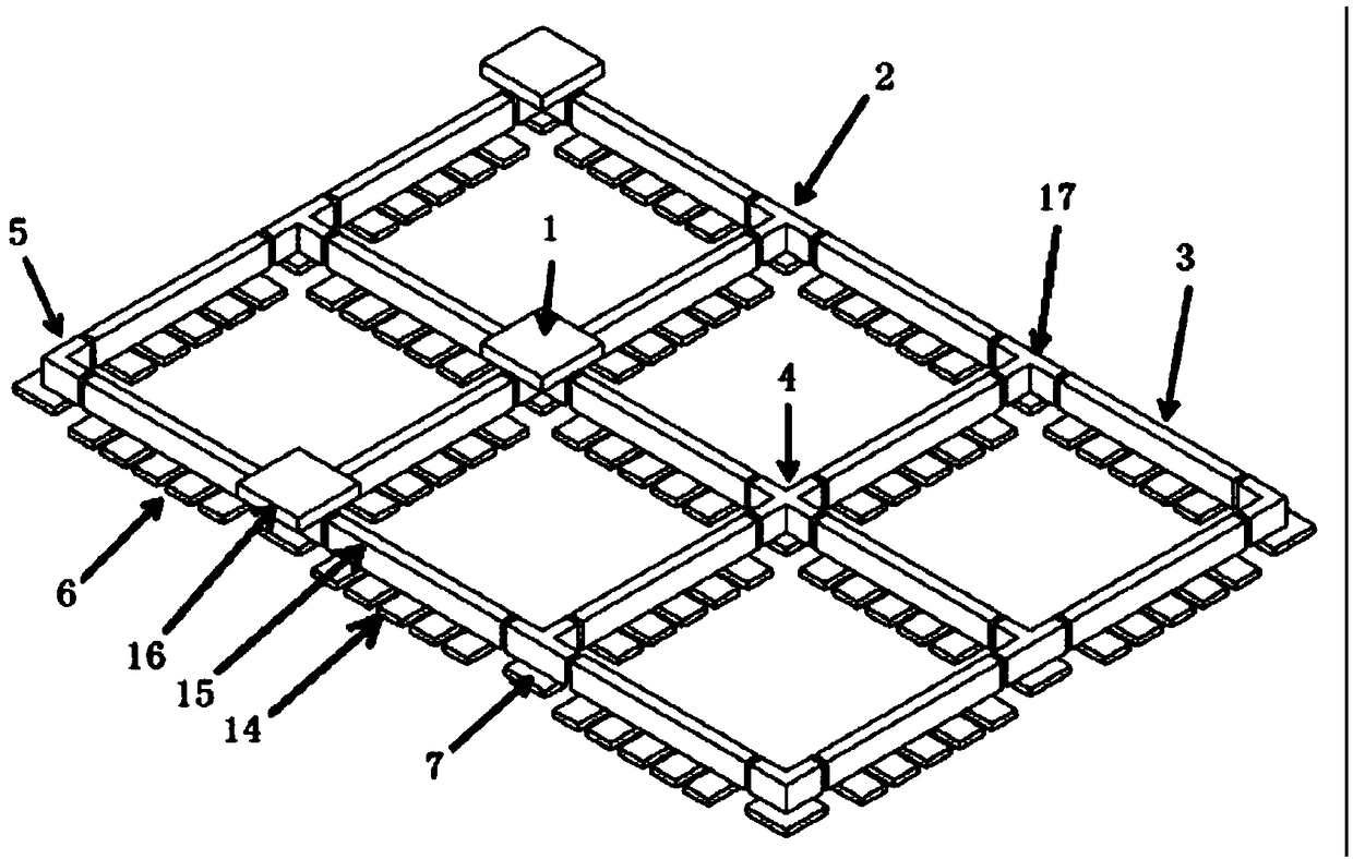
[0038] Below in conjunction with accompanying drawing, the present invention is further described: as figure 1 The equipment-assembled beam foundation shown in , is provided with a floor layer 14, a connecting beam layer 15, and an abutment layer 16 in sequence from bottom to top, and each layer of components is assembled and spliced ​​by modular components on site. Modular components can be prefabricated in concrete or in other materials. After modularization, the specifications of each component are standardized, and the volume is small, which is convenient for any replacement of the same model during transportation and on-site assembly, thus greatly reducing the cost of materials.

[0039] The bottom plate layer 14 is spliced ​​piece by piece by the modular straight beam bottom plate 6 and the node beam bottom plate 7, as figure 1 In the embodiment, the straight beam bottom plate 6 can be a rectangular prefabricated plate, and the node beam bottom plate 7 can be a square p...


PUM


Abstract

Provided are an equipment fabricated beam foundation and a construction method thereof. A bottom plate layer, a connecting beam layer and an abutment layer are sequentially arranged from bottom to top. Each layer of component is assembled and spliced on site through a modular component. The bottom plate layer is formed by sequentially splicing a modular straight beam bottom plate and a joint beambottom plate block by block. Straight beam bottom plates and joint beam bottom plates are connected with beams through vertically through bolt holes, the horizontal degree of the beams is adjusted, the lower portions of corner beam sections are connected with the joint beam bottom plates, and the lower portions of straight beams are connected with straight beam bottom plates. Abutments are arranged above corner beam sections and fixedly connected with the corner beam sections below the abutments, and are used for containing equipment. A brand-new equipment foundation construction manner is provided, so that construction of the equipment foundation is very fast, safe, stable and extremely small in differential settlement, full-modular and on-site fabricated type dry construction can be achieved, and the construction cost is greatly reduced.

Description

technical field [0001] The invention relates to the technical field of construction, in particular to an equipment-assembled beam foundation and a construction method thereof. Background technique [0002] The construction of the equipment foundation needs to take into account the installation and use of the equipment. For larger equipment or the need for fixed connections between equipment, the requirements for the settlement difference between equipment are relatively strict. Therefore, the equipment requires a stable foundation. At present, the foundation is generally designed as a cast-in-place concrete foundation, but this method requires a large amount of concrete, a long construction period, and many wet operations on site, and does not meet the requirements of the prefabricated operation advocated by the state. Contents of the invention [0003] The technical problem to be solved by the present invention is to provide an equipment-assembled beam foundation and its...

Claims


Application Information

Patent Timeline
IPC IPC(8): E02D27/44
CPCE02D27/44
Inventor 王小平陆波程春英黄涛
Owner HUBEI BIEYIGE STEEL STRUCTURE TECH DEV
Why Eureka
Try Eureka