
Swash plate bearing structure used for compressor

A technology for compressors and swash plates, which is applied in the field of compressors and can solve problems affecting the service life of swash plate compressors, high friction, and wear of swash plates and piston seats, so as to prevent the increase of friction and improve the use of Life, friction reduction effect

Pending Publication Date: 2018-11-06
杭州新亚低温科技有限公司
View PDF4 Cites 1 Cited by
  • Summary
  • Abstract
  • Description
  • Claims
  • Application Information

AI Technical Summary

Problems solved by technology

[0004] However, in the above technical solution, the swash plate and the piston seat are in a sliding connection, resulting in a relatively large frictional force between the two, and further, the swash plate and the piston seat are prone to wear and tear, which affects the service life of the swash plate compressor.

Method used


Image

  • Swash plate bearing structure used for compressor
  • Swash plate bearing structure used for compressor

Examples


Embodiment Construction

[0031] The present invention will be described in further detail below in conjunction with the accompanying drawings.

[0032] In the drawings of the embodiments of the present invention, the same or similar symbols correspond to the same or similar components; The orientation or positional relationship indicated by etc. is based on the orientation or positional relationship shown in the drawings, and is only for the convenience of describing the present invention and simplifying the description, rather than indicating or implying that the referred device or element must have a specific orientation, use a specific Orientation structure and operation, therefore, the terms describing the positional relationship in the drawings are only for illustrative purposes, and should not be construed as limitations on this patent. Those of ordinary skill in the art can understand the specific meanings of the above terms according to specific situations.

[0033] A swash plate bearing struc...


PUM


Abstract

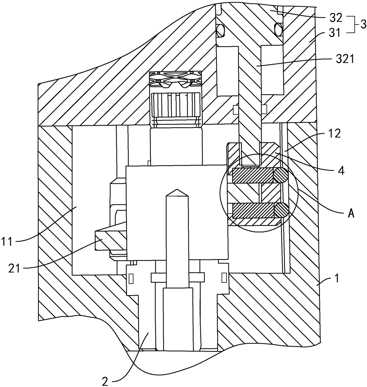
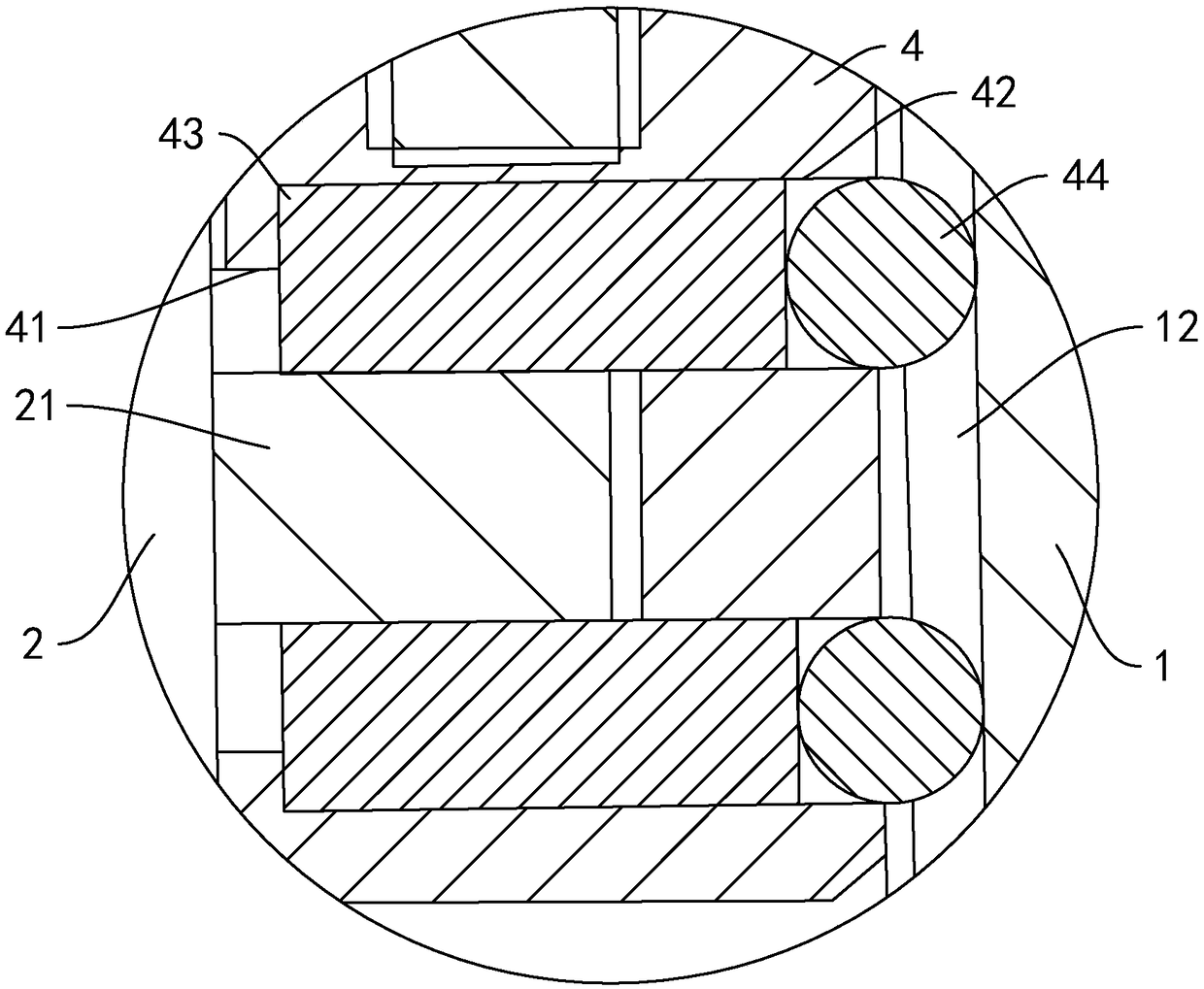
The invention discloses a swash plate bearing structure used for a compressor and belongs to the field of compressors. By means of the structure, the problems that friction force between a swash plateand a piston seat is large, and consequentially, the swash plate and the piston seat are prone to being abraded is solved. According to key points of the technical scheme of the structure, the structure comprises a shell; the shell is fixedly connected with an air cylinder; the air cylinder is in sliding connection with a piston and is rotationally connected with a spindle; the spindle is fixedlyconnected with a swash plate; the piston is fixedly connected with a piston seat; a connecting groove is formed in the piston seat; the edge of the swash plate is arranged in the connecting groove; and rolling components are arranged between the piston seat and the swash plate and roll between the piston seat and the swash plate. The swash plate bearing structure is reasonable in structure, sliding friction between the piston seat and the swash plate is converted into rolling friction by means of the rolling components, accordingly, the friction force between the swash plate and the piston seat is reduced, and abrasion between the swash plate and the piston seat is reduced.

Description

technical field [0001] The present invention relates to a compressor, more specifically, it relates to a swash plate bearing structure for a compressor. Background technique [0002] The swash plate compressor relies on the rotary motion of the swash plate inclined to the rotating shaft to drive the piston or piston rod to reciprocate to achieve gas compression. The bolt-type swash plate is used to convert the torque of the main shaft into reciprocating axial sliding . [0003] At present, the bolted swash plate shaft structure, such as figure 1 , including a cylinder, the cylinder is slidably connected with a piston, the cylinder is rotatably connected with a main shaft, the main shaft is fixedly connected with a spiral swash plate, the piston is fixedly connected with a piston seat, and the piston seat is provided with a connecting groove, so The edge of the spiral swash plate is placed in the connecting groove. When the main shaft rotates, it drives the swash plate to ...

Claims


Application Information

Patent Timeline
Patent Type & Authority Applications(China)
IPC IPC(8): F04B27/08F04B39/00
CPCF04B27/0865F04B27/0869
Inventor 章轶明安丽丽刘易孙立东马晓燕
Owner 杭州新亚低温科技有限公司
Learn More