A Design Optimization Method of Centrifugal Fan

A technology of centrifugal fan and optimization method, which is applied in the direction of mechanical equipment, machine/engine, liquid fuel engine, etc., and can solve problems such as inefficiency, excess, and high research and development costs

Active Publication Date: 2020-04-28
北京龙度风科技有限责任公司
View PDF5 Cites 0 Cited by
  • Summary
  • Abstract
  • Description
  • Claims
  • Application Information

AI Technical Summary

Problems solved by technology

This type of fan generally focuses on the control of noise, but does not consider the issue of efficiency.
At the same time, compared with the industrial field, this type of product often pursues appearance design, which has caused many geometric restrictions on the design of its internal power provider - the centrifugal fan
The traditional design method relying on the similar laws of fluid machinery cannot be applied here because there are no mature fan models that can be referred to, and the aerodynamic design of a new fan is completely beyond the capabilities of ordinary manufacturers
Large-scale scientific research units are unwilling to pay too much energy for this type of fan due to its low economic value and relatively high research and development costs.
In addition, the engineering design method of this type of multi-blade centrifugal fan is not very mature, and the design index can only be achieved after many trial calculations, or even cannot be completed, which is time-consuming and laborious

Method used


Image

  • A Design Optimization Method of Centrifugal Fan
  • A Design Optimization Method of Centrifugal Fan
  • A Design Optimization Method of Centrifugal Fan

Examples


Embodiment 1

[0081] Embodiment one ( figure 2 )

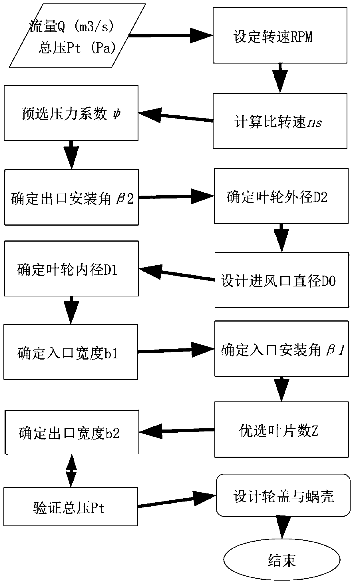
[0082] figure 2 It is a flow chart showing the design of the universal centrifugal fan involved in Embodiment 1 of the present invention.

[0083] Such as figure 2 As shown, the specific steps of the general centrifugal fan design process are as follows:

[0084] Step 1, determine the design flow Q of the centrifugal fan n (m 3 / s) and design total pressure P n (Pa);

[0085] Step 2, set the speed RPM;

[0086] Step 3, calculate the specific speed ns;

[0087] Step 4, pre-select the pressure coefficient ψ;

[0088] Step 5, determine the outlet installation angle β2;

[0089] Step 6, determine the impeller outer diameter D2;

[0090] Step 7, design the air inlet diameter D0;

[0091] Step 8, determine the inner diameter D1 of the impeller;

[0092] Step 9, determine the entrance width b1;

[0093] Step 10, determine the inlet installation angle β1;

[0094] Step 11, preferred blade number Z;

[0095] Step 12, determine the...

Embodiment 2

[0099] Embodiment two ( image 3 )

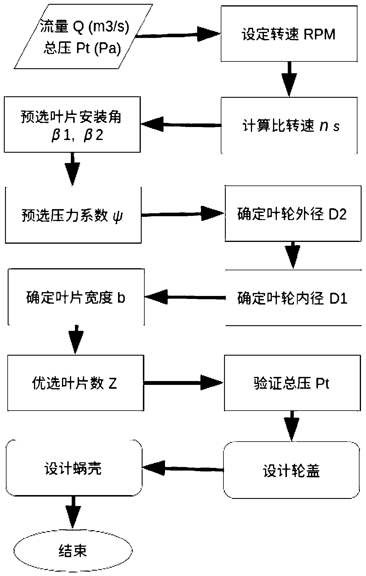
[0100] image 3 It is a flow chart showing the design of the multi-blade centrifugal fan involved in the second embodiment of the present invention.

[0101] The aerodynamic model of the multi-blade centrifugal fan is different from that of a common fan, and the design process described in Embodiment 1 cannot be used. Its feasible design process is as follows: image 3 As shown, the specific steps are as follows:

[0102] Step 1, determine the design flow Q of the centrifugal fan n (m 3 / s) and design total pressure P n (Pa);

[0103] Step 2, set the speed RPM;

[0104] Step 3, calculate the specific speed ns;

[0105] Step 4, preselect blade installation angles β1 and β2;

[0106] Step 5, pre-select the pressure coefficient ψ;

[0107] Step 6, determine the impeller outer diameter D2;

[0108] Step 7, determine the inner diameter D1 of the impeller;

[0109] Step 8, determine blade width b;

[0110] Step 9, preferred blade nu...

Embodiment 3

[0115] Embodiment three ( Figure 4 )

[0116] Figure 4 It is a flow chart showing the design of adjusting the outlet width of centrifugal fan blades of the present invention.

[0117] For non-equal width blades, adjusting the outlet width can change the outlet pressure of the centrifugal fan impeller. Using the steepest descent method, generally satisfactory results can be obtained. The gradient information used at this time is:

[0118]

[0119] For blades of equal width, the width is defined as b=b1=b2, and the gradient information is defined as:

[0120]

[0121] Its feasible design process is as follows: Figure 4 As shown, the specific steps are as follows:

[0122] Step 1, determine the design flow Q of the centrifugal fan n (m 3 / s) and design total pressure P n (Pa);

[0123] Step 2, set the speed RPM;

[0124] Step 3, preselect blade installation angles β1 and β2;

[0125] Step 4, determine the outer diameter D2 of the impeller and the inner diamet...


PUM


Abstract

The invention provides a design optimization method for a centrifugal fan. The method comprises the following steps: determining design indexes of the centrifugal fan, wherein the design indexes comprise a design flow and a design total pressure; establishing an aerodynamic performance function of the centrifugal fan; determining geometrical parameters of the centrifugal fan as the total pressurereaches the design total pressure by means of an optimization algorithm, so that a design scheme meeting the demands is provided.

Description

technical field [0001] The invention belongs to the field of centrifugal fan design, and in particular relates to an aerodynamic engineering optimization method for small and medium-sized centrifugal fans. Background technique [0002] The main application object of the present invention is a centrifugal fan. Especially small and medium-sized centrifugal fans used in civil products such as air conditioners, air purifiers, radiators for electronic equipment, etc. This type of fan generally focuses on the control of noise, but does not pay much attention to the issue of efficiency. At the same time, compared with the industrial field, this type of product often pursues exterior design, which has caused many geometric restrictions on the design of its internal power provider - the centrifugal fan. The traditional design method relying on the similar laws of fluid machinery cannot be applied here because there are no mature fan models that can be referred to, and the aerodynam...

Claims


Application Information

Patent Timeline
Patent Type & Authority Patents(China)
IPC IPC(8): F04D25/08F04D27/00F04D29/30F04D29/00
CPCF04D25/08F04D27/002F04D27/003F04D29/002F04D29/30
Inventor 秦晓龙
Owner 北京龙度风科技有限责任公司
Why Eureka
Try Eureka