Hollow blade structure and design method of aeroengine

An aero-engine and hollow blade technology, which is used in machines/engines, liquid fuel engines, mechanical equipment, etc., can solve problems such as hollowing and weight reduction of hollow blade structures, and achieve overall weight reduction, improvement of stable working boundaries, and simplification of manufacturing. Effects of Difficulty and Detection Difficulty

Active Publication Date: 2020-06-05
AVIC BEIJING AERONAUTICAL MFG TECH RES INST
View PDF6 Cites 0 Cited by
  • Summary
  • Abstract
  • Description
  • Claims
  • Application Information

AI Technical Summary

Problems solved by technology

In order to improve the working efficiency of the compressor, the concept of hollow fan blades was proposed, and part of the material inside the blade body was removed to reduce the structural weight of the blades. Studies have shown that the weight reduction efficiency of the hollow blades is related to the spanwise size of the blades. At present, the hollow fan blades The weight reduction efficiency of the blade varies between 12% and 46%. However, the current technology is not able to hollow the tenon and the Schengen area, which restricts the further reduction of the weight of the hollow blade structure

Method used


Image

  • Hollow blade structure and design method of aeroengine
  • Hollow blade structure and design method of aeroengine
  • Hollow blade structure and design method of aeroengine

Examples


Embodiment Construction

[0032] In order to make the purpose, technical solutions and advantages of the embodiments of the present invention clearer, the technical solutions in the embodiments of the present invention will be clearly and completely described below in conjunction with the drawings in the embodiments of the present invention. Obviously, the described embodiments It is a part of embodiments of the present invention, but not all embodiments. Based on the embodiments of the present invention, all other embodiments obtained by persons of ordinary skill in the art without creative efforts fall within the protection scope of the present invention.

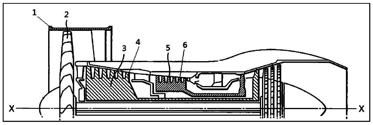
[0033] figure 1 It is a schematic diagram of the structure of an aviation turbojet engine.

[0034] Aeroengine is the main power device of aircraft, such as figure 1 As shown, the aviation turbojet engine mainly includes a rotating part and a stator part, and the rotating part mainly includes a fan 2, a low-pressure compressor disc 3, a high-pre...


PUM


Abstract

The invention relates to a hollow blade structure of an aero-engine and a design method of the hollow blade structure. The hollow blade structure is characterized in that a blade is of a hollow structure, and comprises a blade aerodynamic configuration surface, an internal reinforcing rib structure and airflow holes positioned on the blade back side of the blade; an reinforcing rib penetrates through the blade body part of the blade; through the internal reinforcing rib structure, an internal airflow channel which changes in the blade spreading direction is formed and the airflow holes penetrate through the skin of a metal plate on the blade back side, so that airflow in the internal airflow channel can circulate with air on the blade back side through the airflow holes; a dovetail tenon is adopted for the blade; and a tenon through hole communicating with the hollow area of a blade body is formed in the bottom of the dovetail tenon. Through a way to arrange the reinforcing rib structure in the hollow blade structure, the airflow channel is formed; meanwhile, the airflow holes are designed in the blade back side of the blade, so that airflow in the airflow channel can be discharged(or sucked) and then a boundary layer on the blade back side can be eliminated; and accordingly, the entire weight of the blade can be reduced, the aerodynamic efficiency of the aero-engine can be improved, and the advanced aero-engine performance requirements can be met.

Description

technical field [0001] The invention relates to the technical field of aero turbojet engines, in particular to a hollow blade structure of an aeroengine and a design method thereof. Background technique [0002] The aero-engine is the main power device of the aircraft. When the aero-engine is working, the fan and compressor blades rotate at high speed, increasing the speed and pressure of the air entering the engine. For the fan, part of the pressurized air is discharged at high speed through the external duct of the engine. , to generate thrust, a part of it enters the inner channel of the engine, and after being further pressurized by the low-pressure compressor and the high-pressure compressor, it enters the combustion chamber for combustion. [0003] During the air speed-up and pressurization process by fans and compressors, the air flow is in a reverse pressure gradient flow state, that is, the pressure of the fluid at the outlet of the fan and single-stage compressor i...

Claims


Application Information

Patent Timeline
Patent Type & Authority Patents(China)
IPC IPC(8): F04D29/26G06F30/23G06F30/17
CPCF04D29/26G06F30/17G06F30/23
Inventor 邓瑛李志强
Owner AVIC BEIJING AERONAUTICAL MFG TECH RES INST
Why Eureka
Try Eureka