
Ceiling LED lamp

A technology of LED lamps and ceilings, applied in lighting and heating equipment, semiconductor devices of light-emitting elements, lighting devices, etc., can solve limitations and other problems, and achieve the effect of simple structure and increased interest

Active Publication Date: 2018-11-06
义乌市丹航科技有限公司
View PDF5 Cites 0 Cited by
  • Summary
  • Abstract
  • Description
  • Claims
  • Application Information

AI Technical Summary

Problems solved by technology

[0002] In the prior art, we will set up the ceiling structure indoors. The traditional ceiling structure uses a skeleton, and multiple ceilings are set on the skeleton, and then the ceiling is replaced at the required position and replaced with a ceiling lamp, but After the ceiling light is set up, it is difficult to move it in position, especially in some office areas. Different tenants need different light source positions. If the position of the light source cannot be adjusted at this time, then it can only be selected according to the light source. The location of the office is very limited

Method used


Image

  • Ceiling LED lamp
  • Ceiling LED lamp
  • Ceiling LED lamp

Examples


Embodiment Construction

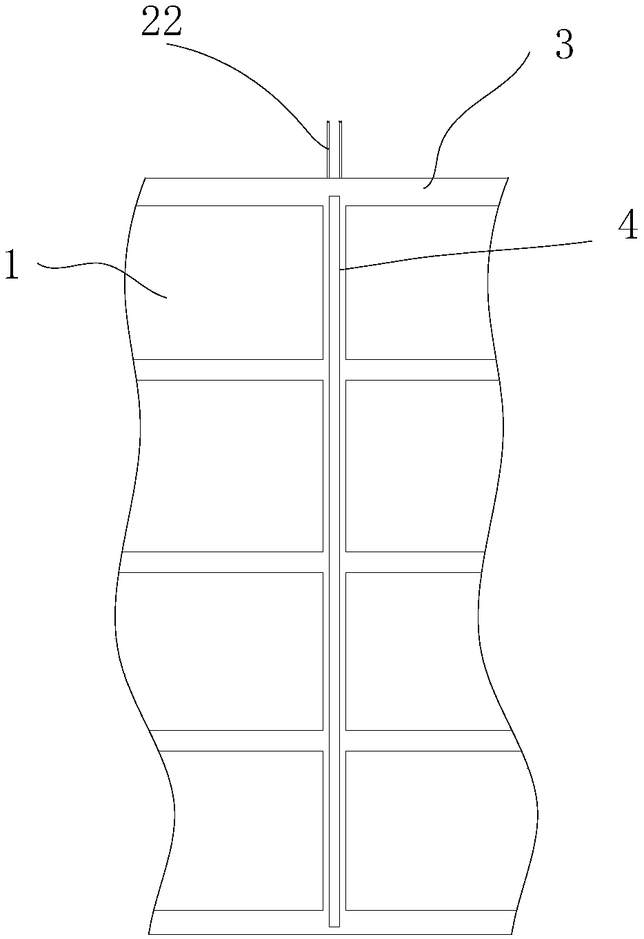
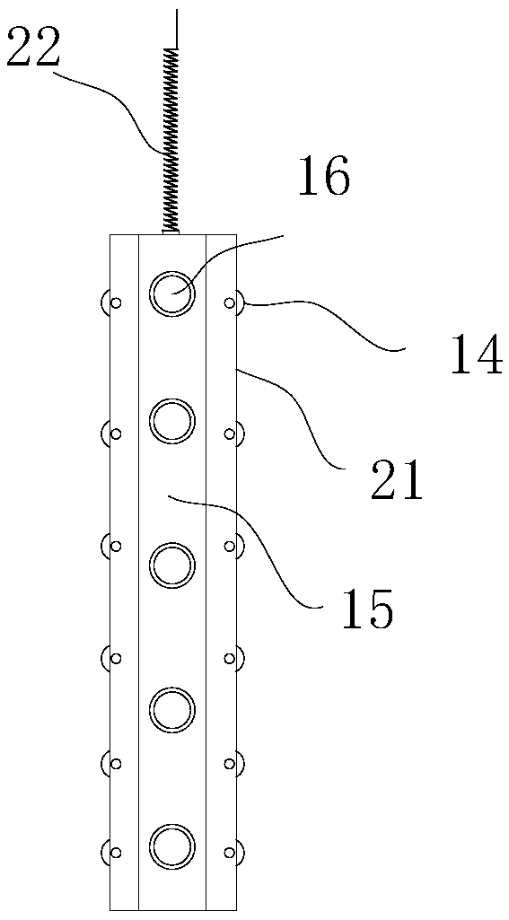
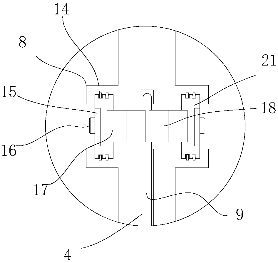
[0017] Such as figure 1 As shown, the ceiling LED lamp includes a ceiling frame 3, and more than one installation cavity 7 is arranged in the middle of the ceiling frame 3, and a ceiling 1 is installed in each installation cavity 7, and the bottom surfaces of two adjacent installation cavities 7 are provided with There are two extension plates 8 up and down, and a moving cavity is formed between the two extending plates 8. A mobile light-emitting device 66 is rolled and installed in the moving cavity, and a guide rail communicating with it is provided on the lower end of the ceiling frame 3 facing the moving cavity. Cavity 4, the guide rail cavity 4 is set on the ceiling frame 3 between two ceilings 1, and the mobile light emitting device 66 is connected to the indoor power supply through its independent power line. Facing the ceiling 1 on both sides.

[0018] Among them, such as image 3 with Figure 4 As shown, the mobile light-emitting device includes a connecting piece ...


PUM


Abstract

The invention discloses a ceiling LED lamp. The ceiling LED lamp comprises a ceiling framework, mounting cavities with the number being one or greater than one are formed in the middle of the ceilingframework, each mounting cavity is internally provided with a ceiling, the bottom surfaces of every two adjacent mounting cavities are each provided with two extending plates arranged up and down, a moving cavity is formed between each pair of extending plates arranged up and down, and a moving light emitting device is installed in each moving cavity in a rolling mode; and a guide rail cavity communicating with the corresponding moving cavity is formed in the position, right opposite to the corresponding moving cavity, of the lower end face of the ceiling framework, and each guide rail cavityis formed in the part, between the two corresponding ceilings, of the ceiling framework. According to the ceiling LED lamp, the structure is simple, all the ceiling structures are improved so that thewhole light source can be moved only by dragging a pulling wire, namely, the position where the whole light source arrive is a light emitting position, the mode is very flexible, the interestingnessis increased, reasonable control over an illumination area is achieved, and the light source position required by a user can be obtained.

Description

technical field [0001] The invention relates to the field of interior decoration lighting, in particular to a ceiling LED lamp. Background technique [0002] In the prior art, we will set up the ceiling structure indoors. The traditional ceiling structure uses a skeleton, and multiple ceilings are set on the skeleton, and then the ceiling is replaced at the required position and replaced with a ceiling lamp, but After the ceiling light is set up, it is difficult to move it in position, especially in some office areas. Different tenants need different light source positions. If the position of the light source cannot be adjusted at this time, then it can only be selected according to the light source. The location of the office is very limited. Contents of the invention [0003] The technical problem to be solved by the present invention is to provide a ceiling LED lamp. All the ceiling structures are improved so that the entire light source can be moved as long as the pul...

Claims


Application Information

Patent Timeline
IPC IPC(8): F21S8/02F21V21/04F21V19/00F21Y115/10
CPCF21S8/026F21V19/001F21V21/049F21Y2115/10
Inventor 徐连芳
Owner 义乌市丹航科技有限公司
Learn More