Air conditioner system, control method thereof and air conditioner

An air-conditioning system and controller technology, which is applied to the control input involving air characteristics, space heating and ventilation control input, heating and ventilation control system, etc. The effect that meets the needs of use

Active Publication Date: 2018-11-06
ANHUI MEIZHI PRECISION MFG
View PDF5 Cites 14 Cited by
  • Summary
  • Abstract
  • Description
  • Claims
  • Application Information

AI Technical Summary

Problems solved by technology

[0002] At present, in related technologies, such as refrigeration systems such as two-stage compression, independent compression, and quasi-two-stage compression, a flasher is used to separate the enthalpy-increasing gas in a small refrigeration device. There are throttling devices before and after the flasher. Convenient, such as figure 1 Shown, be provided with electronic expansion valve 4 ' between flasher 6 ' and condenser 8 ', be provided with capillary 2 ' between flasher 6 ' and evaporator 10 '; figure 2 As shown, a capillary 2' is set between the flasher 6' and the condenser 8', and an electronic expansion valve 4' is set between the flasher 6' and the evaporator 10'; the disadvantage is that the capillary can only It is optimized for a certain working condition, but cannot be optimized for other operating conditions. For example, when heating, if the rated heating condition is optimized with a capillary tube, then the low temperature condition is not optimal, and the more the temperature deviates from the rated heating condition , the farther away from the optimal point

Method used


Image

  • Air conditioner system, control method thereof and air conditioner
  • Air conditioner system, control method thereof and air conditioner
  • Air conditioner system, control method thereof and air conditioner

Examples


Embodiment Construction

[0060] In order to understand the above objects, features and advantages of the present invention more clearly, the present invention will be further described in detail below with reference to the accompanying drawings and specific embodiments. It should be noted that the embodiments of the present application and the features in the embodiments may be combined with each other in the case of no conflict.

[0061] Many specific details are set forth in the following description to facilitate a full understanding of the present invention. However, the present invention can also be implemented in other ways different from those described herein. Therefore, the protection scope of the present invention is not limited by the specific details disclosed below. Example limitations.

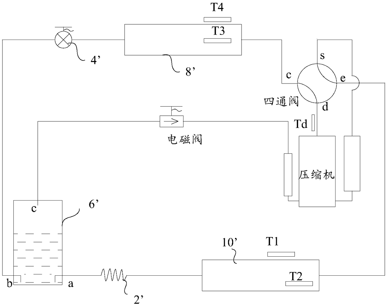
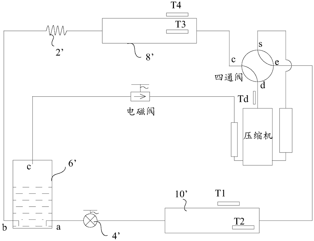
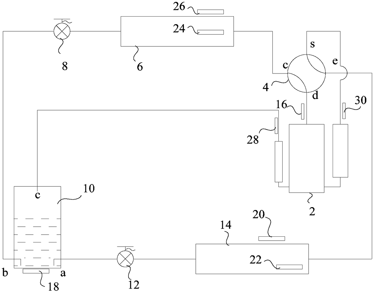
[0062] Refer below Figure 3 to Figure 9 Air conditioning systems and air conditioners provided in accordance with some embodiments of the invention are described.

[0063] An embodiment of the present...


PUM


Abstract

The invention provides an air conditioner system, a control method thereof and an air conditioner. The air conditioner system comprises a compressor, a four-way valve, an outdoor heat exchanger, an indoor heat exchanger, a flash evaporator, a first electronic expansion valve, a second electronic expansion valve and connecting pipes which are connected in sequence. The first electronic expansion valve is arranged between the outdoor heat exchanger and the flash evaporator. The second electronic expansion valve is arranged between the indoor heat exchanger and the flash evaporator. An exhaust temperature sensor is arranged between the compressor and the four-way valve. A flash evaporation temperature sensor is arranged on the flash evaporator or the pipe connected with the flash evaporator.The controller is connected with the exhaust temperature sensor, the flash evaporation temperature sensor, the first electronic expansion valve and the second electronic expansion valve. Through the air conditioner system provided by the invention, under different working conditions, by controlling the opening degrees of the two electronic expansion valves, the throttling conditions of coolants inpipes on the condensation side and the evaporation side of the air conditioner are adjusted, and then the air conditioner system can operate under the optimal conditions.

Description

technical field [0001] The present invention relates to the field of air conditioning systems, and in particular, to an air conditioning system, a control method of the air conditioning system, and an air conditioner. Background technique [0002] At present, in related technologies, such as two-stage compression, independent compression, quasi-two-stage compression and other refrigeration systems, flashers are used to separate enthalpy-increasing gases in small refrigeration devices, and there are throttling devices before and after the flasher. convenient, as figure 1 As shown, an electronic expansion valve 4' is arranged between the flasher 6' and the condenser 8', and a capillary 2' is arranged between the flasher 6' and the evaporator 10'; figure 2 As shown, a capillary 2' is arranged between the flasher 6' and the condenser 8', and an electronic expansion valve 4' is arranged between the flasher 6' and the evaporator 10'; the disadvantage is that the capillary can on...

Claims


Application Information

Patent Timeline
Patent Type & Authority Applications(China)
IPC IPC(8): F24F11/89F24F11/00F24F110/10
CPCF24F11/00F24F11/89F24F2110/10
Inventor 冯利伟廖四清王小龙
Owner ANHUI MEIZHI PRECISION MFG
Why Eureka
Try Eureka