Vacuum induction smelting furnace

A technology of vacuum induction melting and melting chamber, which is applied in the direction of furnace, crucible furnace, furnace type, etc. It can solve the problems of difficult vacuuming, large furnace cavity volume, complex furnace structure, etc., and achieve the effect of reasonable structure

Pending Publication Date: 2018-11-06
SUZHOU ZHENHU ELECTRIC FURNACE +1
View PDF6 Cites 2 Cited by
  • Summary
  • Abstract
  • Description
  • Claims
  • Application Information

AI Technical Summary

Problems solved by technology

[0003] The smelting and ingot casting of the existing vacuum induction melting furnace are completed in one furnace body, which makes the structure of the furnace body complex, and the cavity of the furnace body is relatively large, making it difficult to vacuumize

Method used


Image

  • Vacuum induction smelting furnace
  • Vacuum induction smelting furnace

Examples


Embodiment Construction

[0018] The specific implementation manners of the present invention will be further described below in conjunction with the drawings and examples. The following examples are only used to illustrate the technical solution of the present invention more clearly, but not to limit the protection scope of the present invention.

[0019] The technical scheme of concrete implementation of the present invention is:

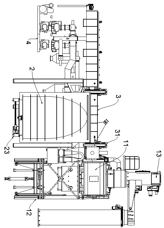
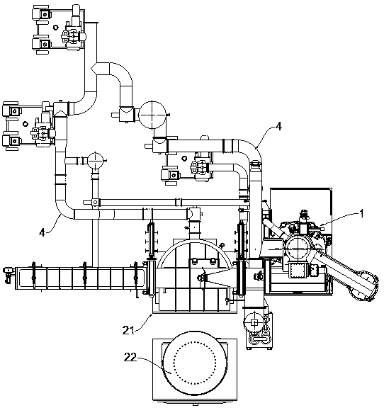
[0020] Such as figure 1 and figure 2 As shown, a vacuum induction melting furnace includes a melting chamber 1 and an ingot casting chamber 2 communicated through a flow channel 3;

[0021] The smelting chamber 1 includes a furnace body 11 supported by a furnace frame 12. A crucible is provided in the furnace body 11. The crucible is equipped with an induction coil. One end of the flow channel 3 extends into the smelting chamber 1. The crucible is located in the flow channel 3. Above, the crucible is also equipped with an overturn drive mechanism that drives it to pour...


PUM


Abstract

The invention discloses a vacuum induction smelting furnace which comprises a smelting room and an ingot casting room communicating through a runner. The smelting room comprises a furnace body which is supported by a furnace rack, wherein a crucible is arranged in the furnace body, an induction coil is arranged on the crucible, one end of the runner stretches into the smelting room, the crucible is located above the runner, and the crucible is also provided with an overturning driving mechanism which drives the crucible to pour molten liquor to the runner. The ingot casting room comprises an upper shell and a lower shell capable of being spliced to each other, wherein the upper shell communicates to the runner, the lower shell is supported by a sliding table which is supported by a slide rail, and the sliding table is provided with a translational driving mechanism which drives the sliding table to translate along a slide rail. The smelting room and the ingot casting room are separately provided with vacuumizing devices, the vacuumizing device arranged in the smelting room is connected to the furnace body, and the vacuumizing device arranged in the ingot casting room is connected to the upper shell; a plurality of filter baffle plates are arranged in the runner, and the filter baffle plates are successively arranged along the stretching direction of the runner. The vacuum induction smelting furnace is reasonable in mechanism and can carry out smelting and ingot casting separately.

Description

technical field [0001] The invention relates to a vacuum induction melting furnace. Background technique [0002] Vacuum induction melting is a method of smelting by using electromagnetic induction to generate eddy currents in metal conductors to heat the charge under vacuum conditions. [0003] The smelting and ingot casting of the existing vacuum induction melting furnace are completed in one furnace body, which makes the structure of the furnace body complex, and the cavity of the furnace body is relatively large, making it difficult to vacuumize. Contents of the invention [0004] The object of the present invention is to provide a vacuum induction melting furnace with a reasonable mechanism, which can separate melting and ingot casting. [0005] In order to achieve the above object, the technical solution of the present invention is to design a vacuum induction melting furnace, including a melting chamber and an ingot casting chamber communicated through a flow chann...

Claims


Application Information

Patent Timeline
Patent Type & Authority Applications(China)
IPC IPC(8): F27B14/06F27B14/08F27B14/14
CPCF27B14/061F27B14/08F27B14/14
Inventor 艾小东朱兴发李亚逸陆钧
Owner SUZHOU ZHENHU ELECTRIC FURNACE
Why Eureka
Try Eureka