Automobile shock absorber performance test bench

A shock absorber and test bench technology, which is applied in the direction of vehicle suspension/shock absorbing mechanism testing, etc., can solve the problems of not being suitable for online production, difficult maintenance, large floor space, etc., and achieve compact structure, short time for changing varieties, and The effect of speed control stabilization

Inactive Publication Date: 2018-11-06
吉林奥拓自动化设备有限公司
View PDF0 Cites 2 Cited by
  • Summary
  • Abstract
  • Description
  • Claims
  • Application Information

AI Technical Summary

Problems solved by technology

Hydraulic vehicle shock absorber performance test bench adopts hydraulic control, which has high cost, large floor area and difficult maintenance. Most of them can only be used in the laboratory and are not suitable for on-line production
Although the traditional mechanical automobile shock absorber performance test bench has solved some shortcomings of the hydraulic automobile shock absorber performance test bench, the speed is fixed, or it can only run at two fixed speeds

Method used


Image

  • Automobile shock absorber performance test bench
  • Automobile shock absorber performance test bench
  • Automobile shock absorber performance test bench

Examples


Embodiment Construction

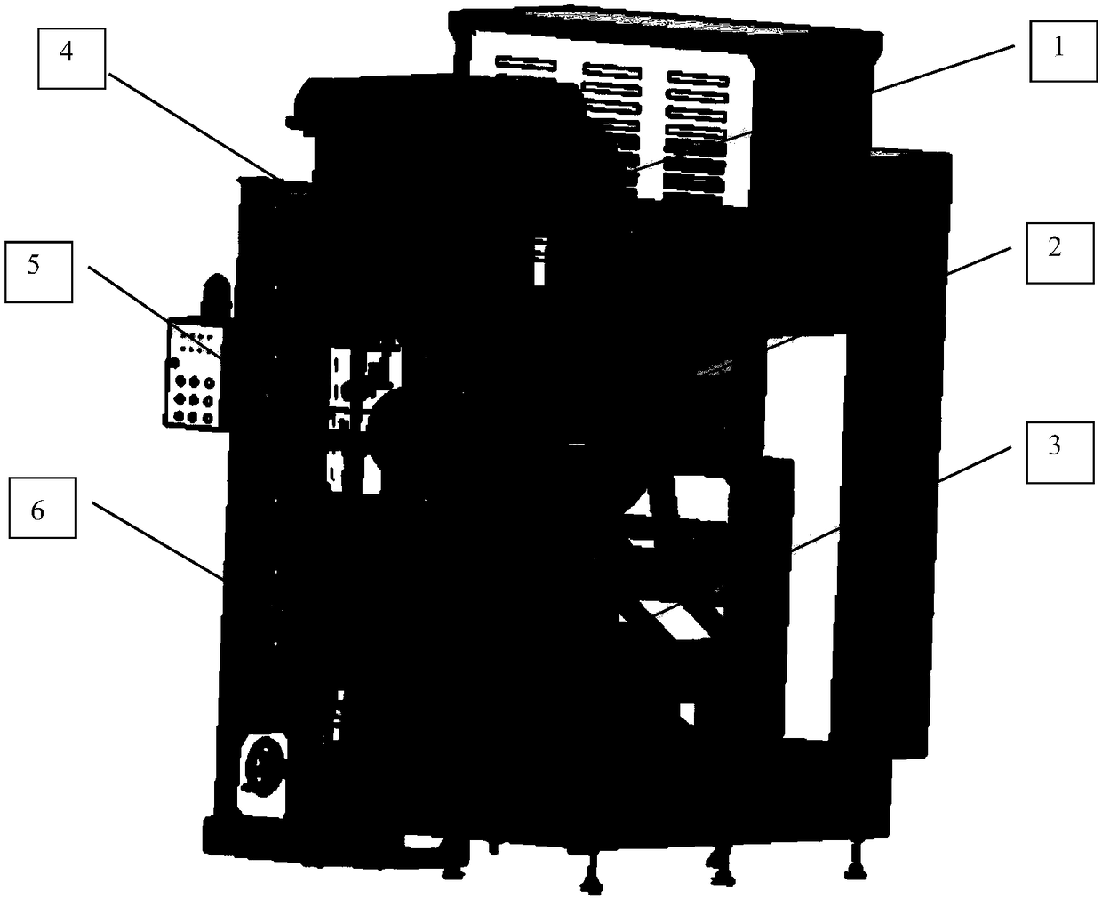
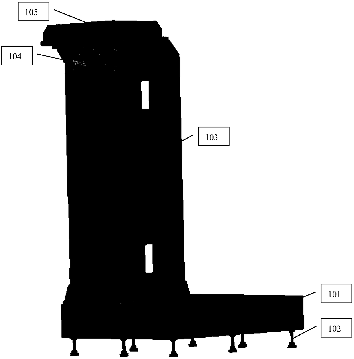
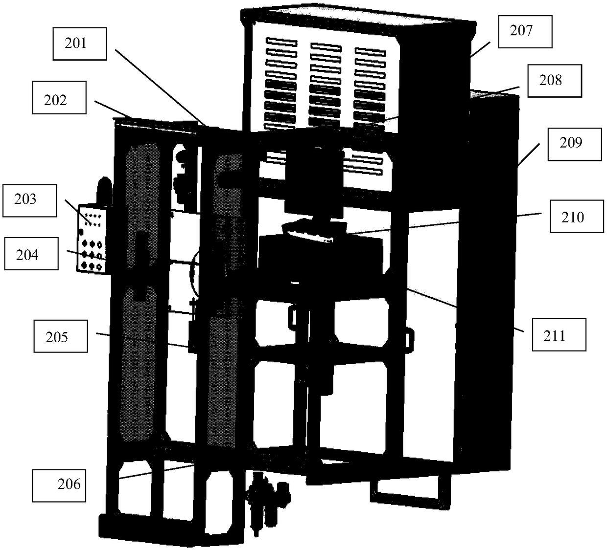
[0014] 1. Refer to figure 1 , figure 2 , image 3 , Figure 4 , Figure 5 , Figure 6 and Figure 7 , a kind of automobile shock absorber performance testing test bench according to the specific embodiment, its composition includes: bed 1, protection and control system 2, power and transmission system 3, upper transmission and force measuring mechanism 4, crank connecting rod and workpiece The clamping adjustment mechanism 5 and the fixture 6; wherein the protection and control system 2, the power and transmission system 3, the upper transmission and force measuring mechanism 4 are connected to the bed 1 through screws; the crank connecting rod and the workpiece clamping adjustment mechanism 5 are connected through The bearing is connected to the transmission shaft of the power and transmission system 3; the fixture 6 is connected to the crank connecting rod and the workpiece clamping adjustment mechanism 5 through the clamping positioning block.

[0015] 2. Refer to ...


PUM


Abstract

The technical scheme of the invention includes a bed, a protection and control system, a power and transmission system, an upper transmission and force measuring mechanism, a crank connecting rod andworkpiece clamping adjustment mechanism and a fixture; the protection and control system, the power and transmission system, and the upper transmission and force measuring mechanism are connected to the bed by bolts; the crank connecting rod and workpiece clamping adjustment mechanism is connected to a driving shaft of the power and transmission system through a bearing; and the fixture is connected to the crank connecting rod and workpiece clamping adjustment mechanism through a clamping positioning block. The function is to realize the approximate sinusoidal harmonic motion by using a servomotor to drive a crank connecting rod mechanism; a force measurement sensor and a displacement sensor measure the damping force of a damper and the displacement of a damper piston rod; an industrial personal computer calculates and analyzes the sensor data, and displays the damper performance result. The invention is high in test efficiency, is suitable for online testing of a production line, iscompact in structure, and is stable and durable.

Description

Technical field: [0001] The invention relates to an automobile shock absorber performance test bench, which belongs to the field of automobile manufacturing equipment, and its main function is to test the damping force of the shock absorber and display the test result with a dynamometer diagram. Background technique: [0002] The damping force of the automobile shock absorber is tested during the production process, and defects in the structure and process of the shock absorber are found. It is required that the equipment can compress and restore the shock absorber, and record and judge the compressive force and restoring force. The performance test bench of hydraulic automobile shock absorber adopts hydraulic control, which has high cost, large floor area and difficult maintenance. Most of them can only be used in the laboratory and are not suitable for on-line production. Although the traditional mechanical automobile shock absorber performance test bench has solved some s...

Claims


Application Information

Patent Timeline
Patent Type & Authority Applications(China)
IPC IPC(8): G01M17/04
CPCG01M17/04
Inventor 付显峰王山苏亚洲臧增旭
Owner 吉林奥拓自动化设备有限公司
Why Eureka
Try Eureka