
A Position Marking Tool for High Frequency Partial Discharge Measurement

A partial discharge, measuring position technology, applied in the direction of measuring devices, electrical measuring instrument parts, measuring electricity, etc., can solve the problem of not clearly recording the last measurement position, inability to reach, etc., to achieve a fixed spray shape, beautiful, and reduced. Small height error, simple and efficient spraying process

Active Publication Date: 2020-11-24
STATE GRID CORP OF CHINA +1
View PDF1 Cites 0 Cited by
  • Summary
  • Abstract
  • Description
  • Claims
  • Application Information

AI Technical Summary

Problems solved by technology

When measuring partial discharge of equipment such as transformers and current transformers, the last measurement location is not clearly recorded in actual work, especially when measuring transformers, it can be measured at the core grounding down conductor or at the clamp grounding down conductor. Moreover, the height of each measurement is not necessarily the same, so it may not be possible to meet the requirement of "keeping the position of each test point consistent"

Method used


Image

  • A Position Marking Tool for High Frequency Partial Discharge Measurement
  • A Position Marking Tool for High Frequency Partial Discharge Measurement
  • A Position Marking Tool for High Frequency Partial Discharge Measurement

Examples


Embodiment Construction

[0027] The present invention will be described in further detail below in conjunction with the accompanying drawings.

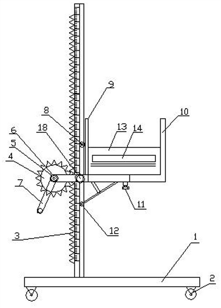
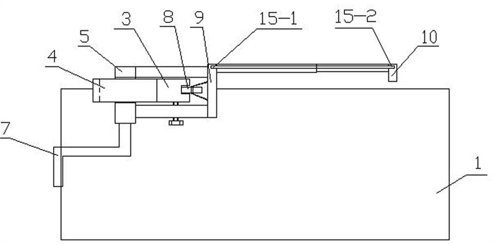
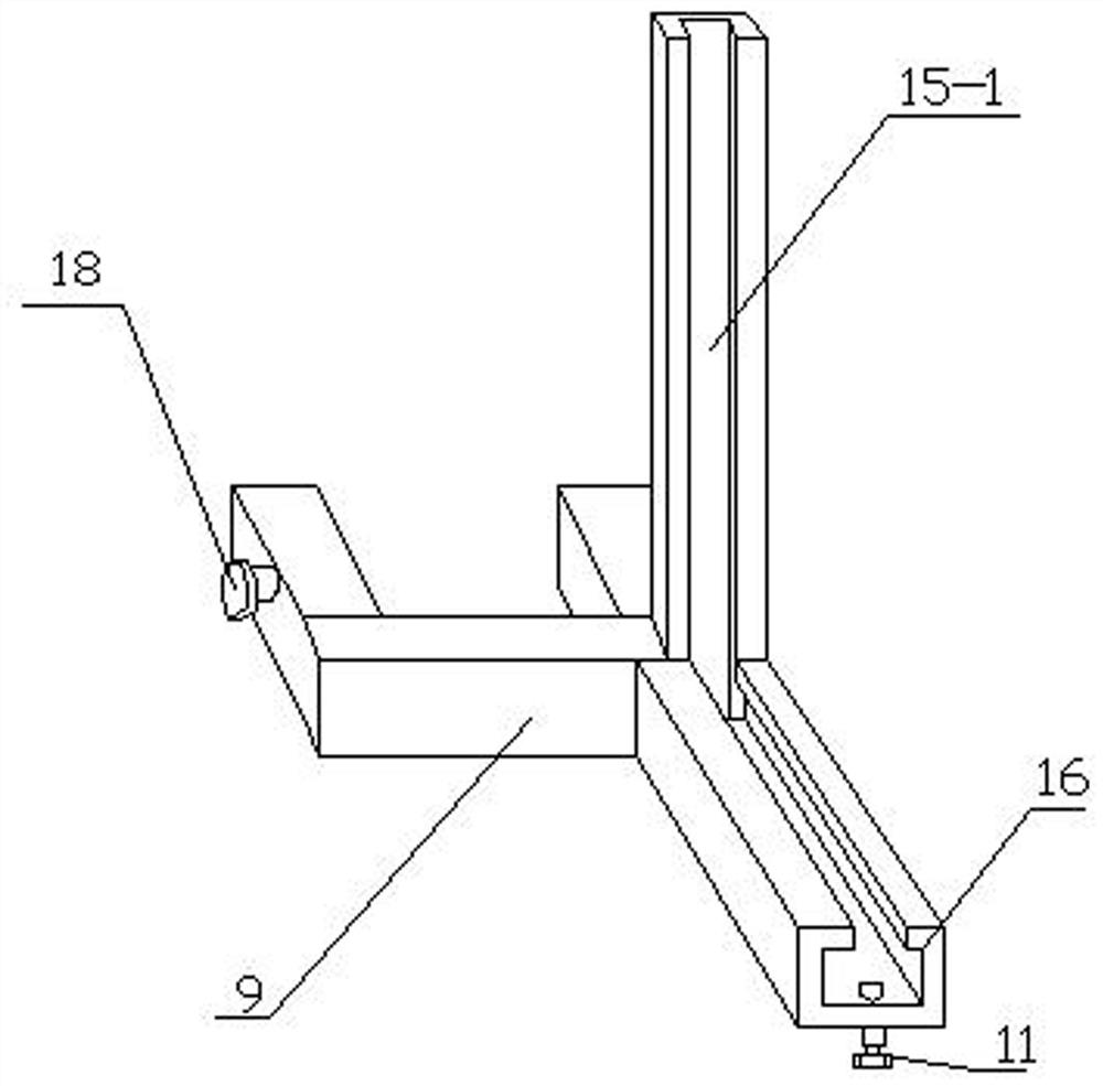
[0028] as attached figure 1 and 2 As shown, a high-frequency partial discharge measurement position marking tool includes a base 1, a traveling universal wheel 2 arranged at the bottom of the base 1, a rack-shaped bracket 3 arranged on the top of the base 1, and a rack-shaped bracket 3 arranged on the bottom of the base 1 The gear 4 on the left, the gear shaft 6 arranged at the axial center of the gear 4, the sleeve 5 and the rotating handle 7 arranged on the gear shaft 6 and the special-shaped frame arranged between the gear 4 and the "L" frame 10 9. The gear shaft 6 and the shaft sleeve 5 are connected by clearance fit, the rotary handle 7 is fixedly connected with the gear shaft 6, and the special-shaped frame 9 is fixedly connected with the shaft sleeve 5; the "L"-shaped frame 10 is provided with a guide groove 15-2 , the upper part of the "L"-shaped fr...


PUM


Abstract

The invention discloses a high-frequency partial discharge measurement position marking tool, which comprises a base, travelling universal wheels arranged at the bottom part of the base, a rack-type support arranged at the upper part of the base, a gear arranged at the left side of the rack-type support, an axle sleeve, a rotating handle, a special-shaped frame, and a guide groove, wherein a height scale is arranged on the rack-type support; the rack-type support is fixedly connected with the base; the axis part of the gear is provided with a gear shaft; the gear and the gear shaft are fixedlyconnected; the axle sleeve is arranged on the gear shaft; the rotating handle is fixedly connected with the gear shaft; the special-shaped frame is arranged between the gear and an L-type frame; theguide groove is arranged in the L-type frame; the special-shaped frame comprises a limiting pin arranged at the right lower part, a guide groove, an open rectangular guide groove, an upper guide wheeland a lower guide wheel; a hard paper board is arranged at the upper part of the L-type frame and the special-shaped frame; and a hollowed word and a hollowed long strip are arranged on the hard paper board, a spraying mark can be positioned, and the spraying marking position is accurate. When devices such as a transformer and a current transformer perform partial discharge measurement, height errors are reduced.

Description

technical field [0001] The invention relates to the field of transformer high-frequency partial discharge measurement and test in substation maintenance. Background technique [0002] Select appropriate test points according to different electrical equipment and site conditions, and keep the same position for each test point, so as to facilitate comparative analysis. When measuring partial discharge of equipment such as transformers and current transformers, the last measurement location is not clearly recorded in actual work, especially when measuring transformers, it can be measured at the core grounding down conductor or at the clamp grounding down conductor. Moreover, the height of each measurement is not necessarily the same, so the requirement of "keeping the position of each test point consistent" may not be met. At the same time, it is required that the marking is simple and practical, and the storage time is long. Contents of the invention [0003] The object of...

Claims


Application Information

Patent Timeline
Patent Type & Authority Patents(China)
IPC IPC(8): G01R31/12G01R1/02
CPCG01R1/02G01R31/1227
Inventor 徐辉沈荣顺胡月琰杨宇王伟王朝阳蒋曦韩若冰宫宁许鹏焦书来李响徐鸣阳白亚楼
Owner STATE GRID CORP OF CHINA
Learn More