Profiled screen panel

A screen panel, special-shaped technology, applied in lighting and heating equipment, instruments, mechanical equipment, etc., can solve the problem of the width of the lower frame, and achieve the effect of reducing the width and increasing the proportion

Inactive Publication Date: 2018-11-06
WUHAN CHINA STAR OPTOELECTRONICS TECH CO LTD
View PDF10 Cites 13 Cited by
  • Summary
  • Abstract
  • Description
  • Claims
  • Application Information

AI Technical Summary

Problems solved by technology

Since the pad area 20 and the LED light bar 30 both occupy part of the w

Method used


Image

  • Profiled screen panel
  • Profiled screen panel
  • Profiled screen panel

Examples


Embodiment Construction

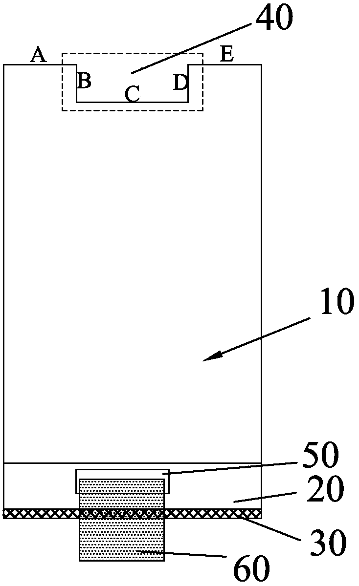
[0027] Based on the problems raised by the background technology, the present invention proposes a design to reduce the lower frame of the special-shaped screen panel and increase the screen ratio of the terminal application, that is, the pad area is set in the groove of the opening / opening position; further, glass can be used Chip-on-chip or chip-on-chip technology connects the pad area and the control circuit system (which may include driver chips, flexible circuit boards, and printed circuit boards); the flexible circuit board can be bent to the back of the panel; and the LED light bar of the backlight system can be Set on the opposite side or the same side as the opening / hole location.

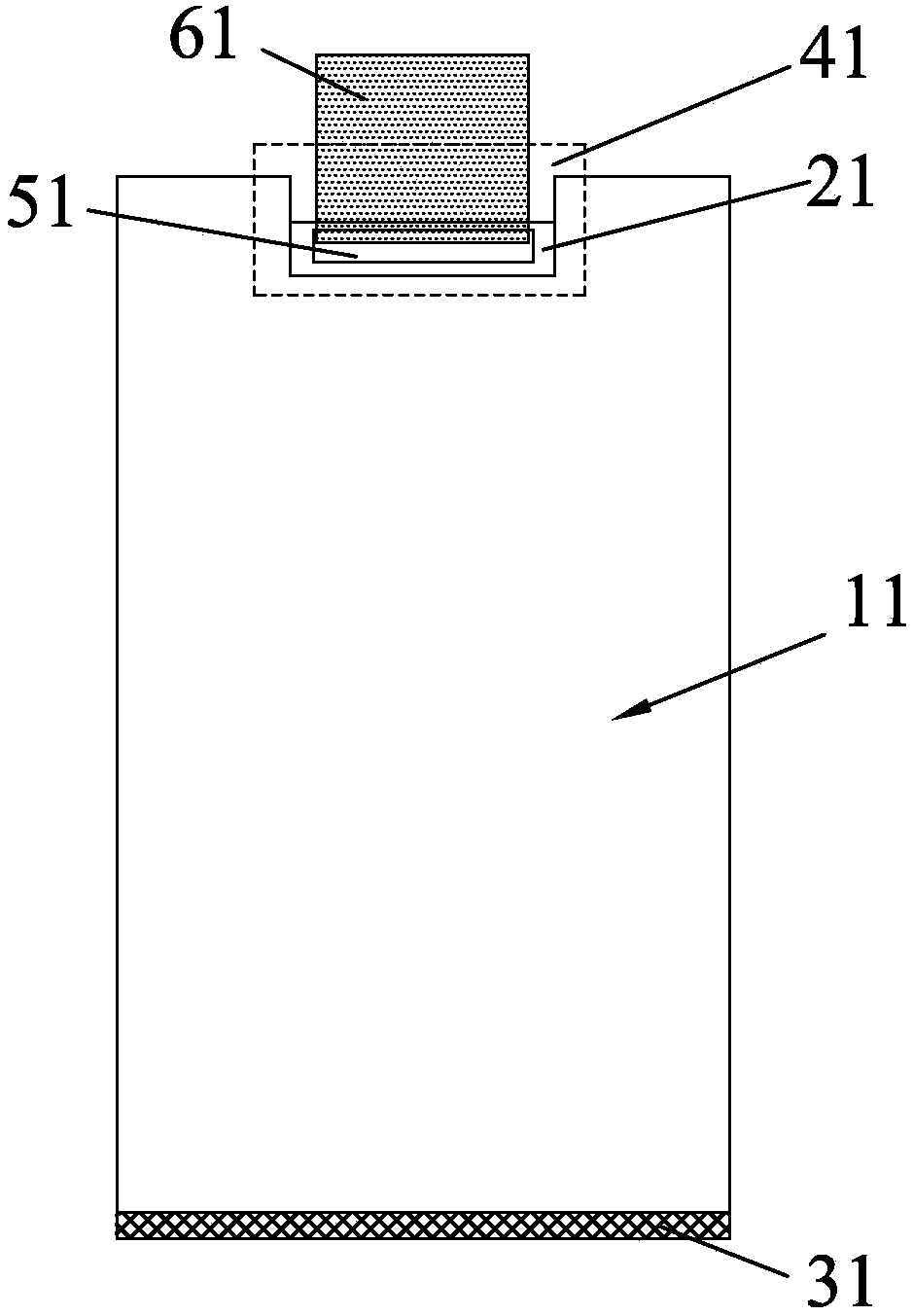
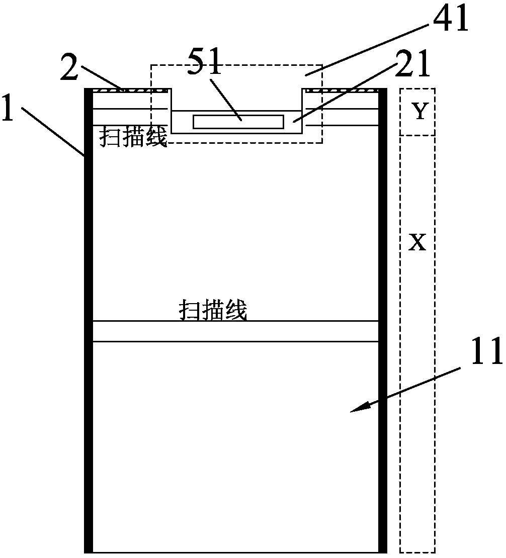
[0028] see figure 2 , which is a schematic structural layout diagram of Embodiment 1 of the special-shaped screen panel of the present invention. The upper end of the panel 11 has a rectangular longitudinal groove 41 formed by an opening / hole design, and the rectangular pad area 21 is di...


PUM


Abstract

The invention relates to a profiled screen panel. The upper end of the profiled screen panel has a longitudinal groove formed by opening/notch design. The bonding pad area of the panel is disposed inthe groove and is provided with a connection terminal. The connection terminal is electrically connected to a driving chip and a flexible circuit board. The flexible circuit board is bent to the backof the panel. The driving chip is pressed against the flexible circuit board by a chip-on-film sealing method, or the driving chip is pressed against a circuit binding region around the connecting terminal by a chip-on-glass packaging method. The width of the lower frame of the profiled screen panel can be effectively reduced; and the ratio of the screen of a terminal is increased.

Description

technical field [0001] The invention relates to the field of display technology, in particular to a special-shaped screen panel. Background technique [0002] With the expansion of the application field of display products, companies that produce display screens or use display screens have begun to design and produce special-shaped screen display products. For example, the IponeX mobile phone has a notch design. The width of the bottom border of the screen panel has not been reduced, and the setting of the opening / opening position has made some users feel that the actual effective area of ​​the panel or the screen-to-body ratio has not increased, which affects the sales of terminal products to a certain extent. [0003] Such as figure 1 As shown, it is a schematic diagram of the structural layout of the existing special-shaped screen panel. The panel 10 has an opening / opening design, mainly including the pad area 20, the LED light bar 30, and the rectangular concave formed ...

Claims


Application Information

Patent Timeline
IPC IPC(8): G02B6/00F21S8/00F21V8/00F21Y115/10
CPCF21S8/00F21Y2115/10G02B6/0066
Inventor 唐岳军
Owner WUHAN CHINA STAR OPTOELECTRONICS TECH CO LTD
Why Eureka
Try Eureka