
Dynamic radio energy transmission system and passive control method thereof

A technology of wireless energy transmission and wireless energy, applied in electric vehicle charging technology, current collectors, electric vehicles, etc., can solve problems such as charging area restrictions, electric vehicles cannot drive, electric vehicles cannot travel long distances, etc., and achieve good followability Effect

Active Publication Date: 2018-11-06
浙江中创天成科技有限公司
View PDF5 Cites 18 Cited by
  • Summary
  • Abstract
  • Description
  • Claims
  • Application Information

AI Technical Summary

Problems solved by technology

The static wireless charging method has strict restrictions on the charging area, and the user must go to the designated area for charging, and during the charging process, the electric vehicle cannot drive
Due to the limitation of the capacity and volume of lithium batteries of electric vehicles, electric vehicles cannot travel long distances. It is an ideal charging method to fully charge electric vehicles in a short period of time. Therefore, static wireless charging facilities are required to provide a high charging power for Shortening the charging time of electric vehicles is a technical difficulty of static wireless charging technology

Method used


Image

  • Dynamic radio energy transmission system and passive control method thereof
  • Dynamic radio energy transmission system and passive control method thereof
  • Dynamic radio energy transmission system and passive control method thereof

Examples


Embodiment Construction

[0046] The present invention will be further described in detail below in conjunction with the accompanying drawings and specific embodiments.

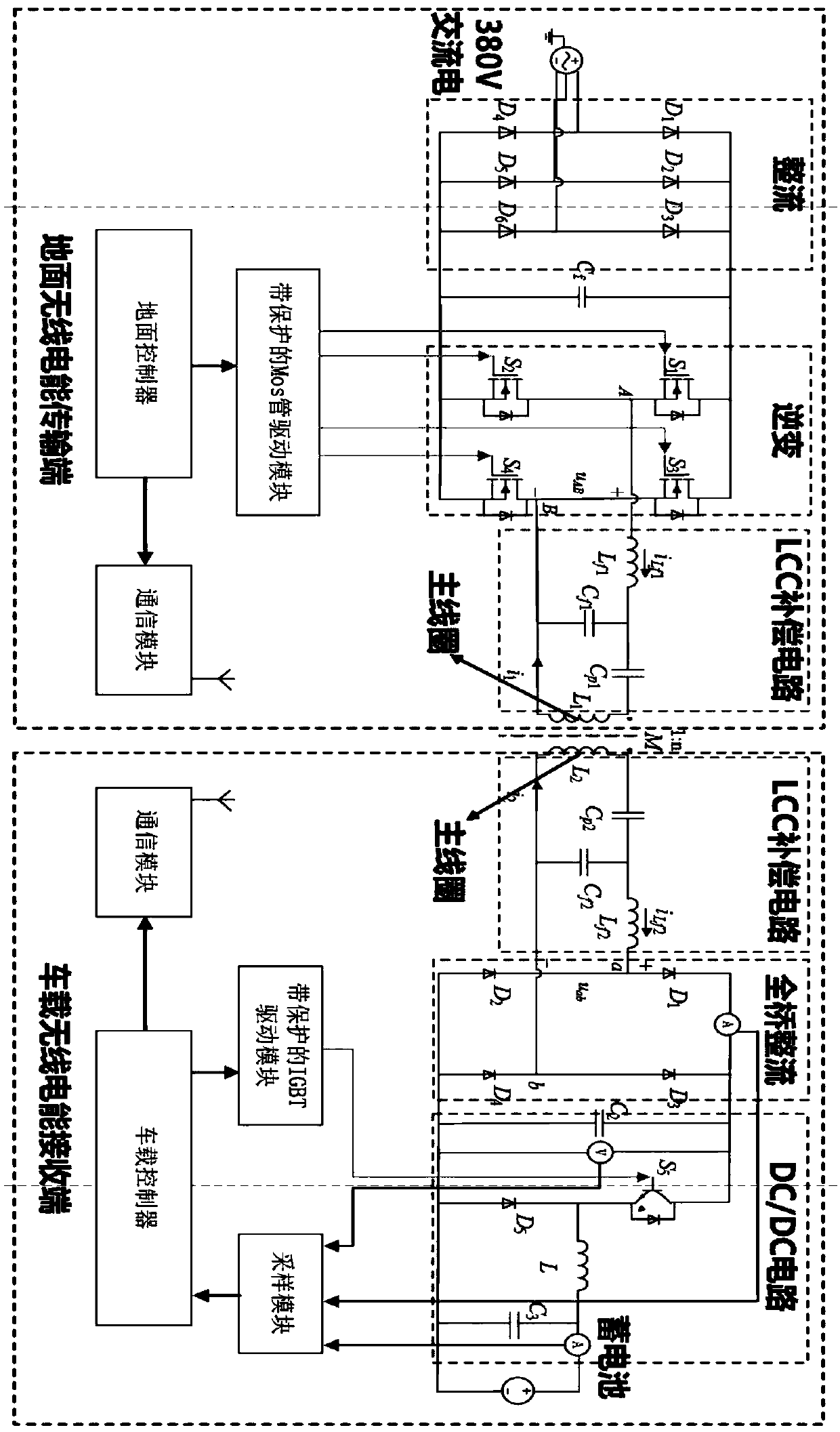
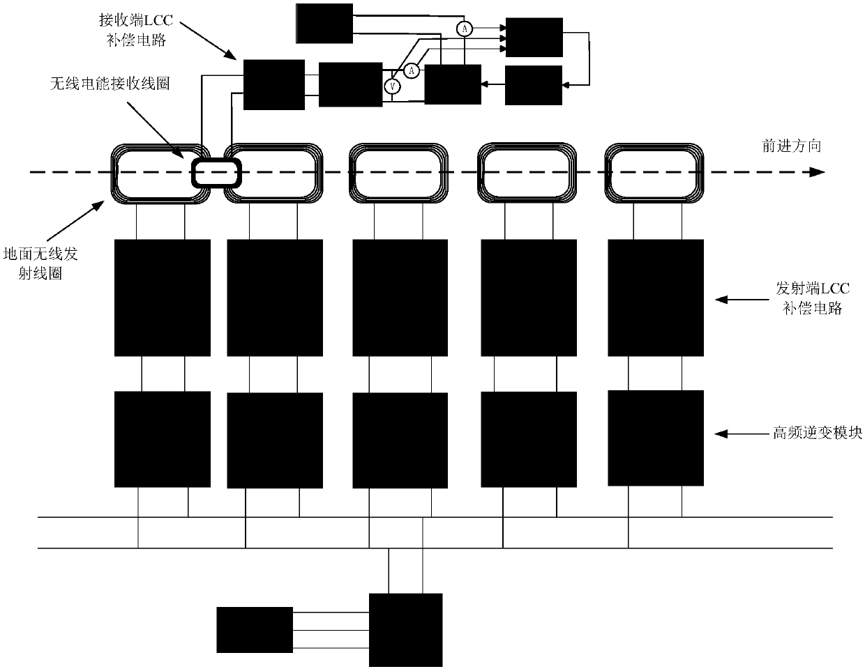
[0047] Such as figure 1 As shown, a dynamic wireless power transmission system provided by the present invention includes a ground wireless power transmission system and a vehicle wireless power receiving system;

[0048] The ground wireless power transmission system is composed of n sets of segmented wireless power transmission devices, and each set of wireless power transmission devices includes a first full-bridge rectifier module, an inverter module, a wireless power transmission module, a transmitter controller and a ground wireless communication module;

[0049] The input end of the first full-bridge rectifier module is externally connected to three-phase alternating current, the input end of the inverter module is connected to the output end of the first full-bridge rectifier module, and the output end of the inverter module i...


PUM


Abstract

The invention discloses a dynamic radio energy transmission system and a passive control method thereof. The system comprises a ground radio energy transmitting system and a vehicle-mounted radio energy receiving system; the ground radio energy transmitting system is composed of n sets of segmented radio energy transmitting devices, and each set of radio energy transmitting device comprises a first full bridge rectifier module, an inverter module, a radio energy transmitting module, a transmitting end controller and a ground wireless communication module; the vehicle-mounted radio energy receiving system comprises a radio energy receiving module, a second full bridge rectifier module, a DC / DC module, a receiving end passive controller and a vehicle-mounted wireless communication module; aradio energy transmitting coil is arranged on a travelling road of an electric vehicle, a radio energy receiving coil is installed on the bottom surface of the electric vehicle; and the dynamic radioenergy transmission system disclosed by the invention adopts a passive control strategy and improves the dynamic properties of the system while ensuring the stability of the system, and the dynamic radio energy transmission system has good followability, rapidity and stability.

Description

technical field [0001] The present invention relates to a dynamic wireless power transmission system, in particular to a dynamic wireless power transmission system and a passive control method thereof. Background technique [0002] With the rapid development of modern society, traditional fossil energy can no longer meet the daily needs of human beings. In addition, traditional fossil energy has also caused serious environmental pollution problems. Therefore, the development of clean energy is imperative. As one of the most important means of transportation in modern society, the problems caused by traditional fuel vehicles have become increasingly prominent. With the rapid increase in the number of vehicles in the world, fossil energy can no longer meet the needs of fuel vehicles, and fuel vehicles have also caused huge damage to the environment. In the context of global environmental degradation and energy shortages, it is increasingly important to develop, promote and ...

Claims


Application Information

Patent Timeline
Patent Type & Authority Applications(China)
IPC IPC(8): H02J7/02H02J50/12H02J50/40H02J5/00B60L11/18
CPCH02J5/005H02J7/025H02J50/12H02J50/40Y02T10/70Y02T10/7072Y02T90/12Y02T90/14Y02T90/16
Inventor 苏宏业马龙华
Owner 浙江中创天成科技有限公司
Learn More