Overcurrent protection circuit

An overcurrent protection circuit, a technology for protecting circuits, applied in circuits, electrical components, electronic switches, etc., can solve problems such as no overcurrent protection function, increased current of PMOS tube P2, hidden dangers, etc.

Pending Publication Date: 2018-11-06
SUZHOU HUAXIN MICROELECTRONICS
View PDF0 Cites 0 Cited by
  • Summary
  • Abstract
  • Description
  • Claims
  • Application Information

AI Technical Summary

Problems solved by technology

[0005] However, the above-mentioned traditional overcurrent protection circuit has the following disadvantages: when the control terminal A is not completely low but in a specific voltage range, the PMOS transistor P1 and the PMOS transistor P2 are not completely turned on, and the integrated circuit pin If the Y1 terminal is connected to a certain range of loads, the current flowing through the PMOS transistor P2 will increase. If it increases to the point where the voltage across R1 reaches the threshold of the comparator COMP1, the output Y2 of the comparator will falsely trigger the protection mechanism.
However, there is no over-current protection function during the period from the moment when the control terminal A completely changes from high level to low level until the output Y2 of the comparator COMP1 can trigger the protection mechanism, and there is a blind zone in the time of the over-current protection function, especially It is an application that requires a very short response time for overcurrent protection, and there are great hidden dangers

Method used


Image

  • Overcurrent protection circuit
  • Overcurrent protection circuit
  • Overcurrent protection circuit

Examples


Embodiment Construction

[0020] The technical solutions of the embodiments of the present invention will be clearly and completely described below in conjunction with the accompanying drawings of the present invention.

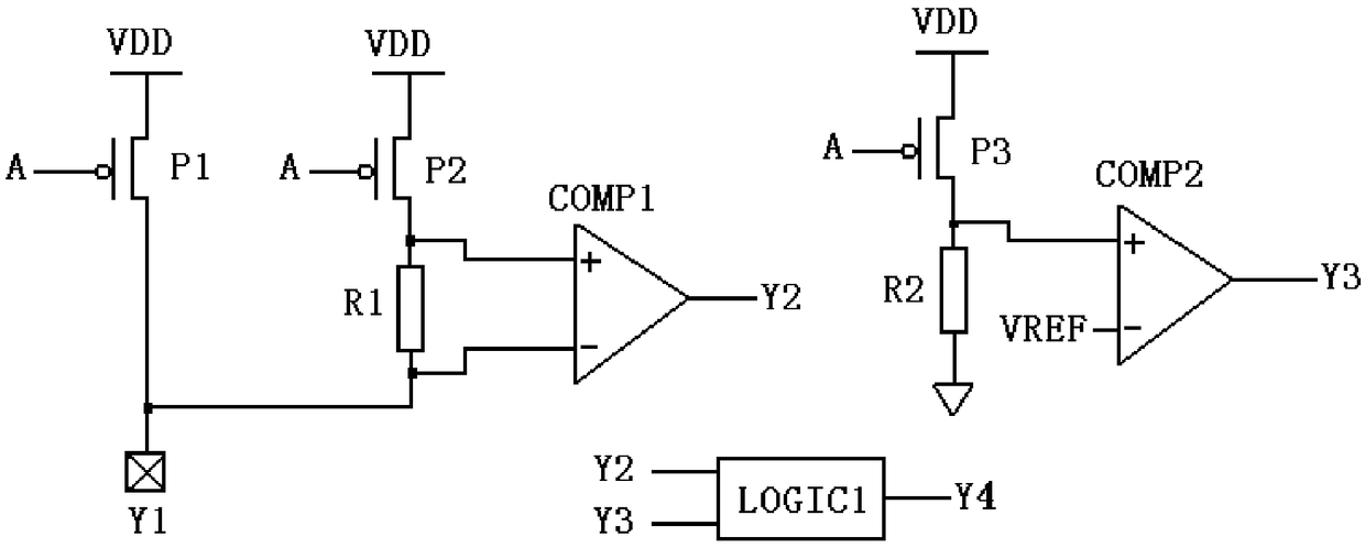
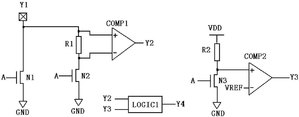
[0021] An overcurrent protection circuit disclosed in the present invention includes a protection circuit body, a logic control circuit, and a conduction detection circuit. The conduction detection circuit is used to detect the conduction of the relevant MOS transistors in the protection circuit body, and controls the chip according to the detection result. Whether to trigger the overcurrent protection mechanism.

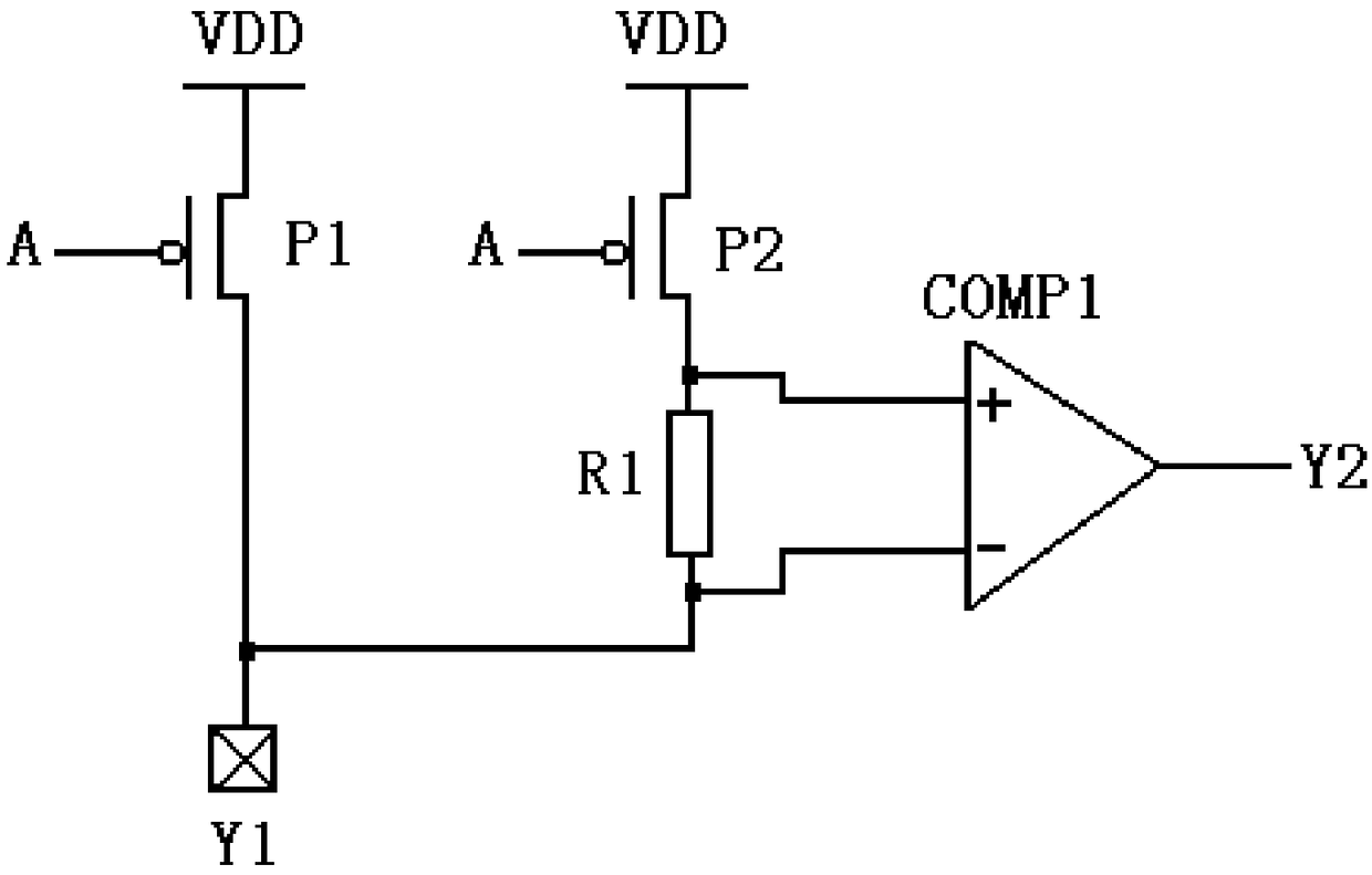
[0022] combine Figure 1 ~ Figure 3 As shown, the protection circuit body disclosed in the embodiment of the present invention is figure 1 The traditional overcurrent protection circuit shown specifically includes a current driver and a current detection module. The current driver can be a first field effect transistor, and the first field effect transistor is a PMOS trans...


PUM


Abstract

The invention discloses an overcurrent protection circuit, comprising a protection circuit body and a conduction detection circuit, wherein the conduction detection circuit is used to detect the conduction state of relevant MOS transistors in the protection circuit body and control whether the protection circuit body triggers an overcurrent protection mechanism according to a detection result. According to the scheme of the invention, the problem that a traditional overcurrent protection method has a blind area in time can be solved.

Description

technical field [0001] The invention relates to an overcurrent protection technology, in particular to an overcurrent protection circuit with fast response and better protection effect. Background technique [0002] Certain integrated circuit pins are prone to misoperation or other reasons lead to excessive current passing through the pins, resulting in adverse consequences, such as damage to the chip or system. Therefore, some integrated circuit pins, especially pins that may pass large currents, need to add over-current protection circuits. [0003] The function of the overcurrent protection circuit is to take certain measures to protect the circuit or system when the current reaches a certain value. Certain measures include but are not limited to shutting down the chip pins or the system, restarting the chip or the system, and returning the pins to normal working status after a certain period of time or after troubleshooting. [0004] figure 1 It is a schematic diagram...

Claims


Application Information

Patent Timeline
Patent Type & Authority Applications(China)
IPC IPC(8): H03K17/081
CPCH03K17/08104
Inventor 石万文魏小康
Owner SUZHOU HUAXIN MICROELECTRONICS
Why Eureka
Try Eureka