Screen sound emission structure for terminal

A screen sounding and screen technology, applied in instruments, sensors, electrical digital data processing, etc., can solve the problems of low frequency difference, poor three-proof performance, low sound pressure, etc., and achieve high sound pressure, good three-proof performance, and low frequency. Effect

Active Publication Date: 2018-11-06
NUBIA TECHNOLOGY CO LTD
View PDF5 Cites 2 Cited by
  • Summary
  • Abstract
  • Description
  • Claims
  • Application Information

AI Technical Summary

Problems solved by technology

[0003] The purpose of the present invention is to provide a screen sounding structure for a terminal, which solves the problems of low sound pressure, low frequency difference, and poor three-proof performance of the terminal screen sounding technology in the prior art

Method used


Image

  • Screen sound emission structure for terminal
  • Screen sound emission structure for terminal

Examples


Embodiment Construction

[0017] The screen sounding structure and specific implementation for the terminal of the present invention will be further described in conjunction with the accompanying drawings and embodiments:

[0018] It should be understood that the specific embodiments described here are only used to explain the present invention, not to limit the present invention.

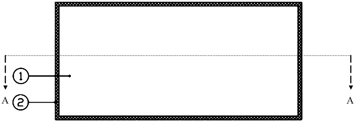
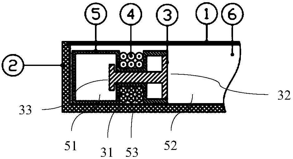
[0019] Such as Figure 1-2 As shown, the present invention relates to a screen sound-generating structure for a terminal. The screen sound-generating structure includes a screen 1 and a rear case 2 , and the screen 1 and the rear case 2 are sealed to form a sealed front cavity 6 . The sealing connection between the screen 1 and the rear case 2 can be achieved by dispensing glue, or by installing a sealing ring or the like. The screen 1 can be an OLED screen, or an LED screen, etc., and it can be slightly deformed. The rear shell 2 can be made of hard metal, such as aluminum alloy, stainless steel, etc., and the hard metal...


PUM


Abstract

The present invention relates to a screen sound emission structure for a terminal. The screen sound emission structure comprises a screen and a rear shell; the screen and the rear shell are in seal connection so as to form a sealed front cavity; a rear cavity for balancing part of the pressure of a gas in the front cavity is defined in the front cavity; a magnetic piston is arranged in the rear cavity; the magnetic piston can move in a reciprocating manner and can be used for compressing the gas in the front cavity, so that a screen can be deformed, and therefore, sound pressure can be generated, and sound is emitted; and a conductive coil that drives the magnetic piston to move through electromagnetic induction is wound around the magnetic piston. According to the screen sound emission structure for the terminal of the invention, the size of the front cavity is large, so that the screen sound emission structure has the advantages of good low frequency effect, large screen area, capability of pushing a large volume of external air and large generated sound pressure; and the screen and the rear shell are sealed to form the front cavity, and therefore, the screen sound emission structure has high three-prevention performance and is not affected by external environment.

Description

technical field [0001] The present invention relates to the technical field of speaker equipment, in particular to a screen sound emitting structure for a terminal. Background technique [0002] With the portability of mobile terminals and Internet access products, the requirements for ultra-thin and ultra-light are getting higher and higher. Existing screen sound mainly includes piezoelectric ceramic technology and motor exciter technology, which have many disadvantages: low sound pressure, It can only be used as an earpiece; the low frequency is poor and the sound is sharp, which is not conducive to long-term listening by the human ear; the three-proof performance is poor and it is easy to fail. Contents of the invention [0003] The object of the present invention is to provide a screen sound emitting structure for a terminal, which solves the problems of low sound pressure, low frequency difference, and poor three-proof performance in the terminal screen sound emitting...

Claims


Application Information

Patent Timeline
Patent Type & Authority Applications(China)
IPC IPC(8): H04R15/00G06F1/16
CPCG06F1/1605H04R15/00
Inventor 丁火根
Owner NUBIA TECHNOLOGY CO LTD
Why Eureka
Try Eureka