Grouting equipment achieving station self-induction time-sharing drive and application method and PLC inner control circuit of grouting equipment

A time-sharing drive and self-sensing technology, which is applied in the field of grouting equipment and PLC internal control circuit, can solve the problems of waiting for a certain time, inaccurate judgment of slurry fullness, and low degree of automation, so as to improve production efficiency and control precision , the effect of high degree of automation

Inactive Publication Date: 2018-11-09
QUANZHOU DEHUA FENGHONG MACHINERY CO LTD +1
View PDF0 Cites 1 Cited by
  • Summary
  • Abstract
  • Description
  • Claims
  • Application Information

AI Technical Summary

Problems solved by technology

The traditional grouting machine uses one or more plaster molds to be placed under the grouting nozzle respectively. The steps of grouting include placing plaster molds, grouting, and removing plaster molds, whether manual or mechanical is used to pick and place plaster molds. , each step must be carried out in sequence, and it takes a certain amount of time to tak

Method used


Image

  • Grouting equipment achieving station self-induction time-sharing drive and application method and PLC inner control circuit of grouting equipment
  • Grouting equipment achieving station self-induction time-sharing drive and application method and PLC inner control circuit of grouting equipment
  • Grouting equipment achieving station self-induction time-sharing drive and application method and PLC inner control circuit of grouting equipment

Examples


Example Embodiment

[0029] The present invention will be further described below through specific embodiments.

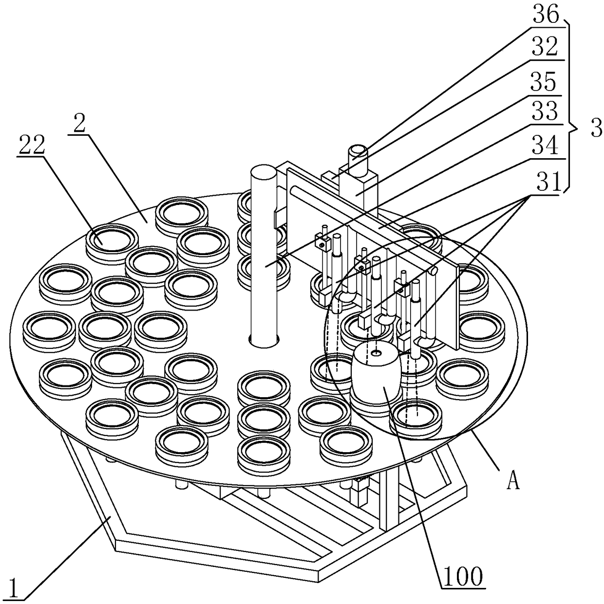
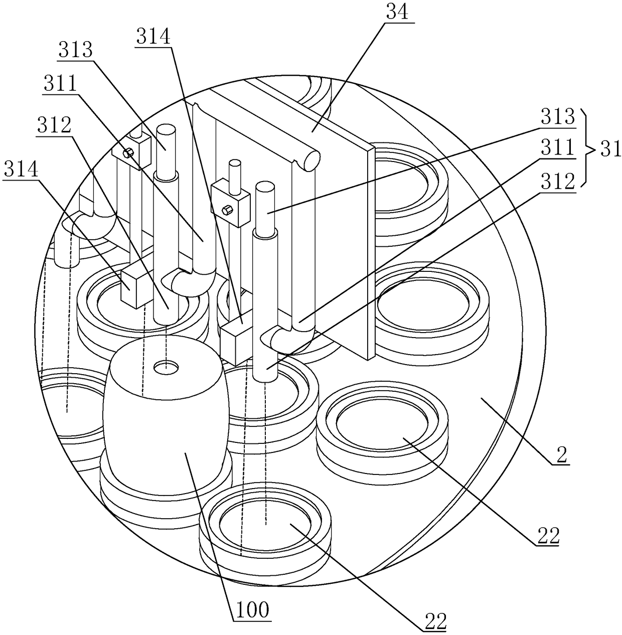
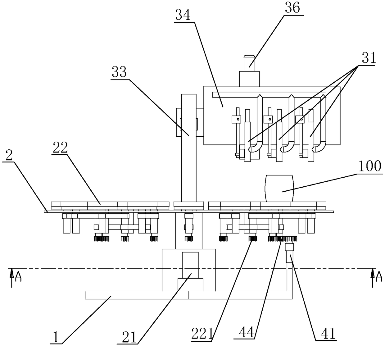
[0030] like Figures 1 to 6 As shown, the station self-induction time-sharing driven grouting equipment of the present invention includes a base 1, a turntable 2 rotatably arranged on the base 1, a grouting device 3 and a power split device 4, and the turntable 2 is driven by a turntable motor 21 Driven to rotate, the turntable motor 21 is connected to the turntable 2 through a reducer. There are multiple grouting disks 22 rotatably arranged on the turntable 2. The grouting device 3 is arranged above the turntable 2. The grouting disk 22 follows the turntable 2 and reaches the injector When the grouting device 3 is below, the grouting disc 22 is connected to the power split device 4, and the grouting disc 22 is connected to the power of the power splitting device 4 and rotates by itself.

[0031] The grouting discs 22 are distributed on the turntable 2 with the axis of rotation of the...


PUM


Abstract

The invention relates to the field of ceramic production equipment, in particular to grouting equipment achieving station self-induction time-sharing drive. The grouting equipment is characterized inthat the grouting equipment comprises a base, a rotating disc rotationally arranged on the base, a grouting device and a power division device; multiple grouting discs are rotationally arranged on therotating disc; the grouting device is arranged above the rotating disc; and when the grouting discs rotate along with the rotating disc and arrive at the position below the grouting device, the grouting discs are connected with the power division device. By means of the equipment, the grouting interval is shortened, the production efficiency is improved, the automation degree is high, and no material overflow condition happens. The invention relates to an application method of the grouting equipment. The production efficiency of ceramic grouting forming can be greatly improved. The inventionrelates to a PLC inner control circuit of the grouting equipment. Whether plaster molds are located on the grouting discs or not and the grout full condition are automatically detected, automatic grouting is achieved, the manual cost is reduced, control is precise, grout cannot overflow, and therefore the problems provided in the background technology are solved.

Description

technical field [0001] The invention relates to the field of ceramic production equipment, in particular to a grouting equipment driven by station self-induction and time-sharing, its use method and its PLC internal control circuit. Background technique [0002] Grouting molding is a method of pouring mud into a plaster mold to make it into a product, which is suitable for batch molding of complex shapes or large products. Its production is roughly as follows: adding water to the ingredients-mud-grouting molding-drying-firing. In modern production, the grouting process is gradually replaced by machine automation or semi-automated production, and vases, pots, teapots, sugar bowls and other complex shapes are formed by grouting. The slurry injection molding method is relatively simple, that is, inject the mud made from the blank into the gypsum model. Because the gypsum board has water absorption, the water in the part of the mud near the inner wall of the model is sucked by ...

Claims


Application Information

Patent Timeline
IPC IPC(8): B28B1/26B28B17/00
CPCB28B1/26B28B1/264B28B17/0081
Inventor 徐智强郑康毅梁仁勇
Owner QUANZHOU DEHUA FENGHONG MACHINERY CO LTD
Why Eureka
Try Eureka