Positioning adjusting frame and laser detection device with same

A technology of positioning adjustment and laser detector, applied in the direction of measuring device, using optical device to transmit sensing components, measuring instrument components, etc. Stability, improve adjustment accuracy, increase the effect of application range

Pending Publication Date: 2018-11-09
SUZHOU RS TECH
View PDF1 Cites 4 Cited by
  • Summary
  • Abstract
  • Description
  • Claims
  • Application Information

AI Technical Summary

Problems solved by technology

[0005] Therefore, the technical problem to be solved by the present invention is to overcome the defect that the laser detection device in the prior art cannot accurately adjust the distance between the laser detector and the surface of the workpiece, thereby providing a device that can accurately adjust the distance between the laser detector and the surface of the workpiece Distance positioning adjustment frame

Method used


Image

  • Positioning adjusting frame and laser detection device with same
  • Positioning adjusting frame and laser detection device with same
  • Positioning adjusting frame and laser detection device with same

Examples


Embodiment 1

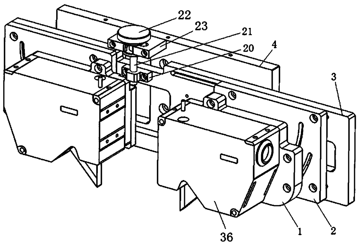
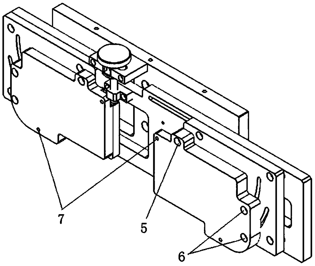
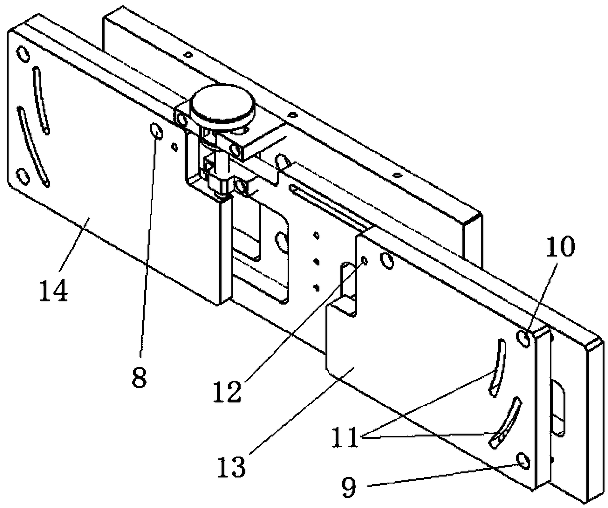
[0080] This embodiment provides a positioning adjustment frame, including an angle adjustment plate 1, a coordinate adjustment plate 2, a height adjustment plate 3, a bottom plate 4 and a height adjustment device.

[0081] There are three through holes for adjusting the angle on the angle adjustment plate 1, and the three through holes are not on the same straight line, one of which is a positioning hole 5, and the other two are angle adjustment holes 6, through which the bolts pass through to adjust the angle. The through hole on the board 1 is connected with the coordinate adjustment board 2, wherein the screw passing through the positioning hole 5 forms a hinge for the angle adjustment board 1 and the coordinate adjustment board 2 before being tightened, and the two screws passing through the angle adjustment hole 6 Before tightening, it can move in an arc with the positioning hole 5 as the center, so that the angle adjustment plate 1 can also slide around the positioning ho...

Embodiment 2

[0104] This embodiment provides a laser detection device, including a laser detector 27 , a positioning adjustment frame and a moving support, and the positioning adjustment frame is the positioning adjustment frame described in Embodiment 1.

[0105] The laser detector 27 is fixed on the angle adjustment plate 1 of the positioning adjustment frame, and the positioning adjustment frame is connected to the moving bracket.

[0106] The mobile support is a cantilever beam type mobile support, comprising: a mobile beam 28 and a fixed support 29 . The moving crossbeam 28 is connected to the fixed support 29 to form a cantilever structure through a linear slide and an electric slide, and the bottom plate 4 of the positioning adjustment frame is connected to the movable crossbeam 28 through another set of linear slides and electric slides. bottom.

[0107] The linear slide table includes a linear guide rail 30 and an aluminum alloy profile 31 . The linear guide rail 30 is fixed on ...


PUM


Abstract

The invention provides a positioning adjusting frame and a laser detection device with the same, and belongs to the technical field of laser detection. The positioning adjusting frame comprises a height adjusting plate, a base plate and a height adjusting device; the height adjusting plate is suitable for installing a laser detector; the base plate is connected to the height adjusting plate through the height adjusting device; and the height adjusting device comprises a first mounting base, a second mounting base and an adjusting screw rod, wherein the first mounting base is fixedly arranged on the height adjusting plate, the second mounting base is fixedly arranged on the base plate, the adjusting screw rod is connected to the first mounting base or the second mounting base in a threadedmode, and the distance between the first mounting base and the second mounting base can be adjusted by screwing the adjusting screw rod. According to the positioning adjustment frame, the height adjusting device is arranged, the height of the mounting bases is adjusted by adjusting threads of the screw rod, so that the adjusting precision of the height of the mounting bases can be improved, and therefore the distance between the laser detector and the surface of a workpiece can be controlled to be more accurate, and the detection effect is improved.

Description

technical field [0001] The invention relates to the technical field of laser detection, in particular to a positioning adjustment frame and a laser detection device having the same. Background technique [0002] Laser detection technology has a very wide range of applications. The use of laser detectors to detect products generally requires first installing the laser detector on the positioning adjustment frame, and then adjusting the position of the laser detector through the positioning adjustment frame so that the laser detector and the detected There is a predetermined distance between products to enable the laser detector to achieve the best detection effect. [0003] Chinese patent document CN104002051A discloses a vertical detection device for laser welding, including a laser displacement sensor, a fixed plate, a connecting plate, a connector and a welding head, and the laser displacement sensor is fixed on the On the welding head, the fixed plate can be adjusted in ...

Claims


Application Information

Patent Timeline
IPC IPC(8): G01D5/26G01D11/30
CPCG01D5/264G01D11/30
Inventor 吴加富缪磊林杰文太平马纪飞李启强
Owner SUZHOU RS TECH
Why Eureka
Try Eureka