Rotary atomizer
A technology of rotating atomizer and atomizing head, which is applied in the direction of instruments, devices using optical methods, indicating/recording actions, etc., and can solve problems such as high capital expenditures
- Summary
- Abstract
- Description
- Claims
- Application Information
AI Technical Summary
Problems solved by technology
Method used
Image

Examples
no. 1 approach
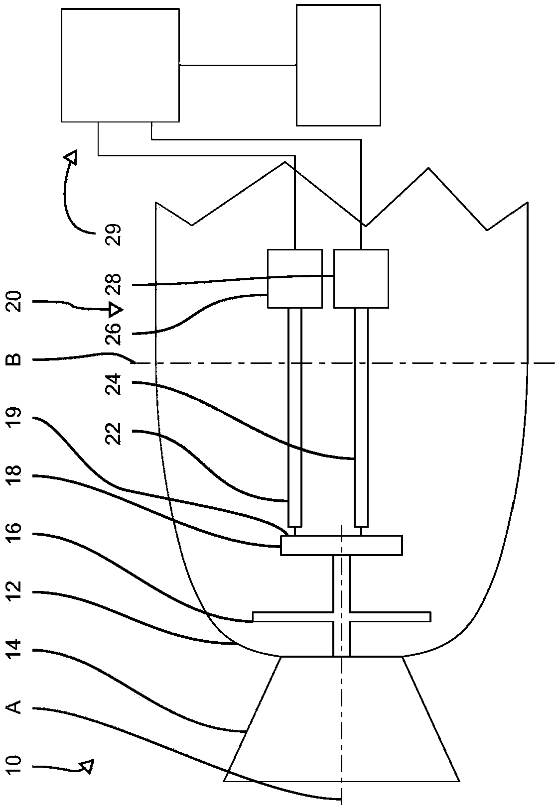
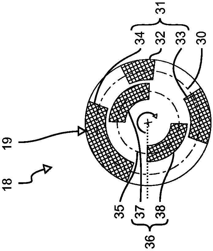
[0036] in figure 1 The first embodiment of the rotary atomizer 10 is shown very schematically in a cross-sectional view, in figure 2 The details of the rotary atomizer 10 are shown in a schematic top view. In the display diagram of the rotary atomizer 10, a housing 12 is shown, which surrounds the main part of the rotary atomizer 10. The rotary atomizer 10 may be, for example, a part of a device for coating a vehicle body (not shown). A bell cup / atomizing head 14 for atomizing a coating material such as lacquer is schematically shown on the front of the housing 12. The atomizing head 14 is rotatably supported around the rotation axis A and is driven by a turbine (not shown) having a turbine 16. The turbine wheel 16 is connected to a rotating body designed as a disk 18 in a rotationally fixed manner.
[0037] The disk 18 is only schematically shown in the cross-sectional view. The disk 18 is a component of the device 20 for determining information related to rotation, such as t...
no. 2 approach
[0049] Figure 4-Figure 6 A second embodiment of the rotary atomizer 100 is shown. Compared with the first embodiment, the same or similar features are indicated by reference numerals increased by 100. In order to avoid repetition, these features will not be described again.
[0050] Unlike the first embodiment, the device 120 for determining information related to rotation of the rotary atomizer 100 of the second embodiment is as Figure 4 A disc 118 is shown, which has a first surface 119 similar to the surface 19 of the rotary atomizer 10 of the first embodiment, and the disc also has a second surface 117 inclined with respect to the first surface 119. The second surface 117 is arranged on the outer edge of the disk 118 in this embodiment and therefore can achieve better signal transmission quality, because less diffuse light of the first surface 119 is coupled into the second optical waveguide body 122 And vice versa.
[0051] As in Figure 5 The distribution of the structure...
no. 3 approach
[0055] in Figure 7-9 A rotary atomizer 200 is schematically shown as the third embodiment. Compared with the first embodiment or the second embodiment, the same or similar features are again indicated by reference numerals increased by 100 or 200.
[0056] in Figure 7 In addition to the known features, the rotary atomizer 200 shown in FIG. also has a device 220 for determining information related to rotation. The difference between this device and the previous embodiment is that it has three optical waveguides 222, 223, and 224. Correspondingly, three photodetectors are provided, symbolically assembled in a unit 228 here.
[0057] Corresponding to the three optical waveguides 222, 223, and 224, the surface 219 of the disc 218 is provided with reflection sections on three circumferential lines 230, 232, and 234 having different radii. On the outermost circumferential line 230 in the current embodiment, 16 reflecting sections 231 are provided, which are arranged equidistantly from...
PUM
 Abstract
Description
Claims
Application Information
 - R&D
- Intellectual Property
- Life Sciences
- Materials
- Tech Scout
- Unparalleled Data Quality
- Higher Quality Content
- 60% Fewer Hallucinations
Browse by: Latest US Patents, China's latest patents, Technical Efficacy Thesaurus, Application Domain, Technology Topic, Popular Technical Reports.
© 2025 PatSnap. All rights reserved.Legal|Privacy policy|Modern Slavery Act Transparency Statement|Sitemap|About US| Contact US: help@patsnap.com