Device for applying abradable material to a surface of a turbomachine casing

A technology of turbine engine and wear-resistant material, which can be used in devices for coating liquid on surfaces, liquid fuel engines, engine components, etc., and can solve the problems of laborious and expensive, long manufacturing process, etc.

Active Publication Date: 2018-11-09
SAFRAN AIRCRAFT ENGINES SAS
View PDF5 Cites 1 Cited by
  • Summary
  • Abstract
  • Description
  • Claims
  • Application Information

AI Technical Summary

Problems solved by technology

[0009] This type of manufacturing process is long, laborious and expensive
Additionally, the knives used for scraping tend to tear the material and create surface imperfections that later need to be filled

Method used


Image

  • Device for applying abradable material to a surface of a turbomachine casing
  • Device for applying abradable material to a surface of a turbomachine casing
  • Device for applying abradable material to a surface of a turbomachine casing

Examples


Embodiment Construction

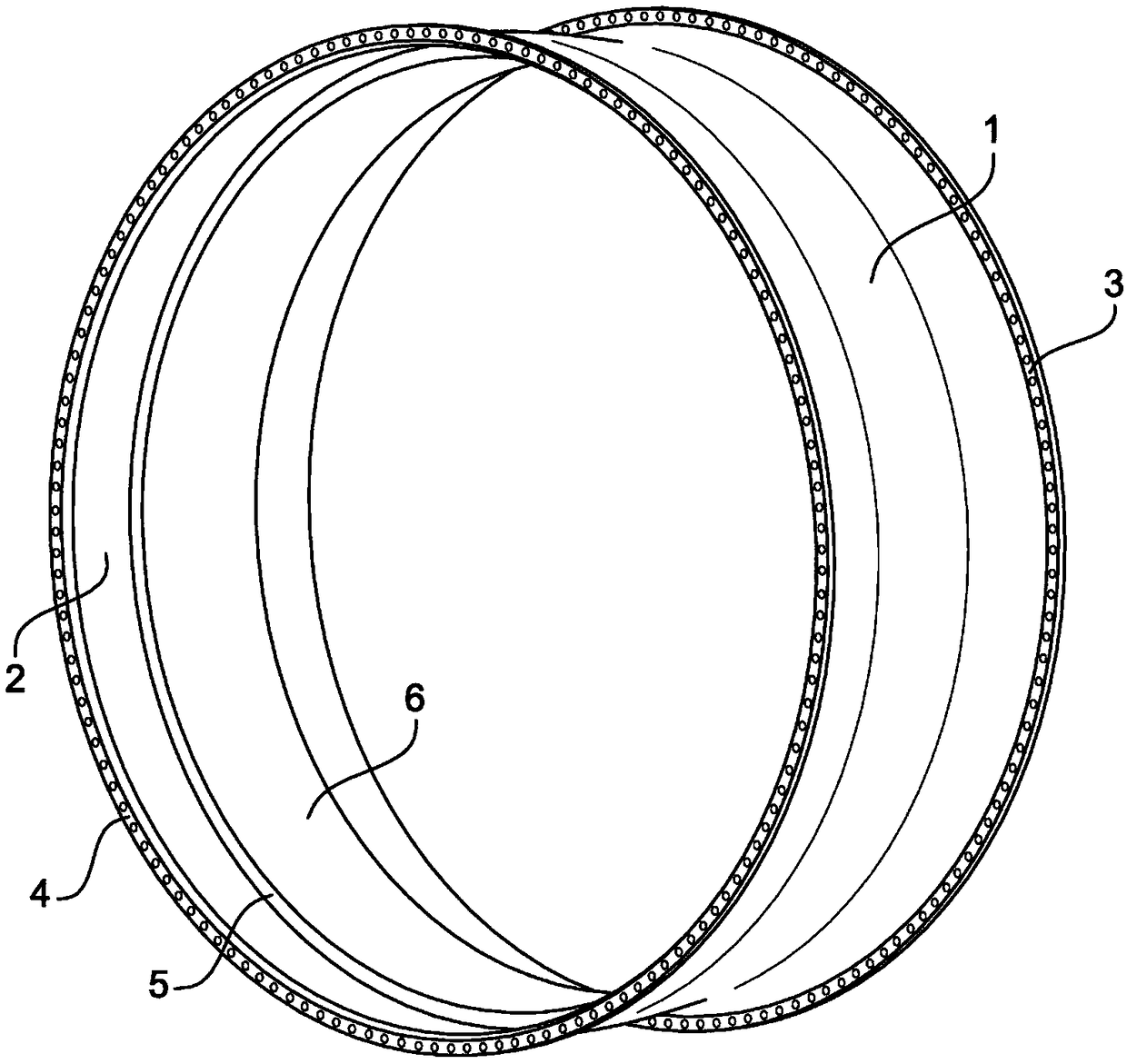
[0044] Figure 4 and Figure 5 A device 11 for applying abradable material is shown for applying abradable material to the surface of the turbine engine housing 1 .

[0045]The device 11 has a support comprising a first part 12 and a second part 13 . When viewed from the front, the first part 12 has an overall U-shape comprising a base 12a from which two branches 12b extend. The free end of each branch 12b has two opposite legs 12c each carrying a guide roller 14 whose axis of rotation 15 is parallel to the base 12a. The first part 12 of the support also comprises an additional branch 12d extending from the lateral end of the base 12a and parallel to the branch 12b. The free end of the additional branch 12d has two opposite legs 12e each carrying a guide roller 16 whose axis of rotation 17 is parallel to the branches 12b , 12d , ie perpendicular to the axis of rotation 15 of the guide roller 14 .

[0046] Two grab handles 18 are fixed to the base 12a, and a handle 19 is fi...


PUM


Abstract

The invention relates to a device (11) for applying abradable material to a surface of an annular casing (1) of a turbomachine, the casing extending along a longitudinal axis. The device (11) comprises a support (12, 13) provided with first guiding means (14) for guiding the support (12, 13) in relation to a casing (1), in a radial direction in relation to the axis of the casing, the support (12,13) being provided with second guiding means (16) for guiding the support (12, 13) in relation to the casing (1) in an axial direction, an application roller (20) being mounted pivotably in relation to the support (12, 13) in the axial direction, and regulating means (22, 23) allowing the position of the roller (20) to be adjusted in relation to the first guiding means (14), in the radial direction.

Description

technical field [0001] The present invention relates to an apparatus for applying an abradable material to a turbine engine casing surface, such as the inner surface of said casing. Background technique [0002] Such as figure 1 As shown, a turbine engine such as an aircraft turbofan engine or C generally comprises a fan casing 1 with a substantially cylindrical wall 2 enclosing in particular the blades of the fan. [0003] The casing 1 forms part of a nacelle which surrounds the electric machine of the turbine engine and inside which rotates a fan which generates a secondary air flow which flows between the nacelle and the electric machine and forms the part of the thrust generated. [0004] The housing 1 comprises a substantially cylindrical wall 2 comprising annular attachment flanges 3, 4 at its longitudinal ends. The downstream flange 4 is attached by screw and nut type to the flange of the intermediate casing (not shown), and the upstream flange 3 is attached by scr...

Claims


Application Information

Patent Timeline
IPC IPC(8): F04D29/02B05C11/02B05C17/02B29C43/46B05C7/00F04D29/16B29C43/28F01D11/12
CPCB05C7/00B05C11/025B05C17/02F01D11/122F04D29/023F04D29/526F05D2230/31F04D29/02F01D11/12B29C43/28B05C11/02B05C7/06
Inventor 理查德·马通拉乌尔·贾索德多米尼克·米歇尔·瑟奇·马格纳迪克
Owner SAFRAN AIRCRAFT ENGINES SAS
Why Eureka
Try Eureka