

Motor-operated valve
An electric valve, valve core technology, applied in the direction of lift valve, valve details, valve device, etc., can solve problems such as deviation
- Summary
- Abstract
- Description
- Claims
- Application Information
AI Technical Summary
Problems solved by technology
Method used
Image

Examples
Embodiment 1
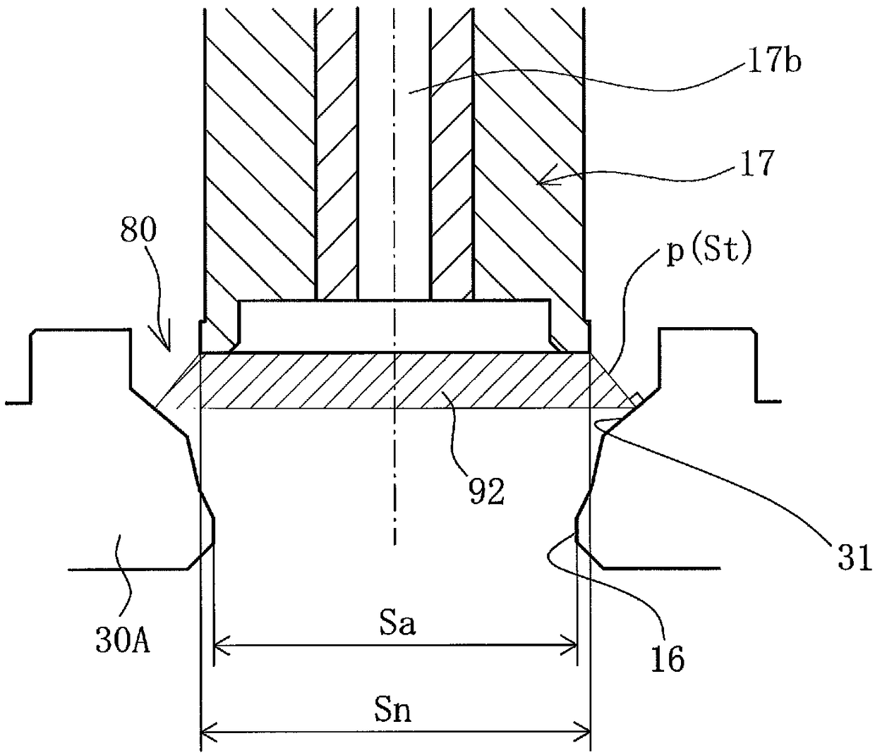
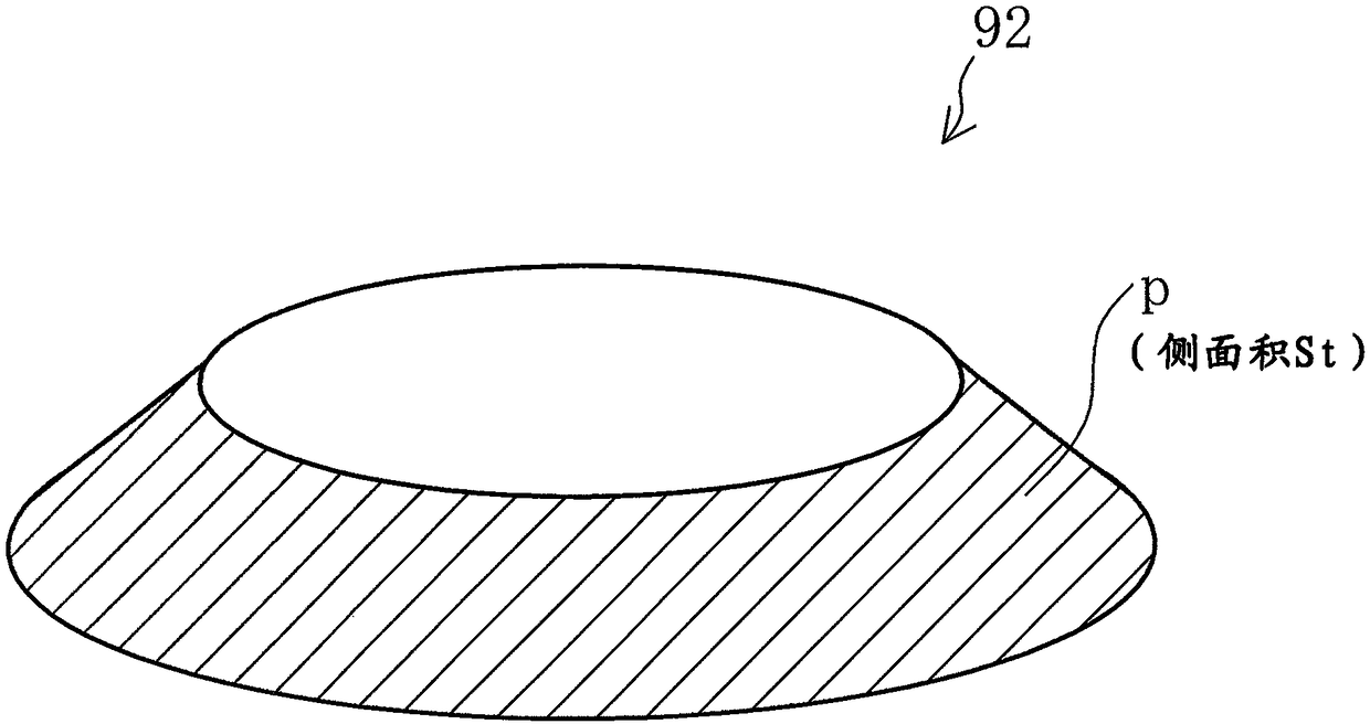
[0058] Figure 4 (a) is a cross-sectional view schematically showing a main part of the electric valve 2 in the first embodiment. Such as Figure 4 As shown in (a), the characteristic surface 31 is inclined outward at a constant inclination angle from the valve port 16 toward the valve body 17 . In addition, the minimum flow path area Sa of the valve port 16 is formed to be smaller than the truncated cone side area Stmax in the fully open state (Sa<Stmax). Thus, by setting Sa<Stmax, whether the fluid is introduced from the spool 17 side and the fluid is taken out from the valve port 16, or the fluid is introduced from the valve port 16 side and the fluid is taken out from the spool 17 side, , the flow rate in the fully open state depends on the minimum flow path area Sa of the valve port 16. Therefore, by designing the electric valve 2 so that Sa<Stmax, the flow rate in the fully open state is only governed by the minimum flow path area Sa of the valve port 16, and is not a...
Embodiment 2
[0065] Figure 6 (a) is a cross-sectional view schematically showing a main part of the electric valve 2 in the second embodiment. Here, the second embodiment is a modified example of the first embodiment, and the description of the same structure as the first embodiment will be omitted, and only the different parts will be described. Such as Figure 6 As shown in (a), the characteristic surface 31 of the valve seat member 30A is inclined outward at a constant inclination angle from the valve port 16 toward the valve body 17 . In addition, an inner peripheral wall 32 is formed on the valve seat member 30A. The inner peripheral wall 32 rises upward from the upper end of the characteristic surface 31 and surrounds the lower end of the valve element 17 in the valve closed state.
[0066] Here, the electric valve 2 of the embodiment 2 is designed so that the side area Stmax of the truncated cone is smaller than the minimum flow path area Sa of the valve port 16 (Stmax
Embodiment 3
[0075] Figure 8 (a) is a cross-sectional view schematically showing a main part of the electric valve 2 in the third embodiment. Such as Figure 8 As shown in (a), regarding the electric valve 2, in the electric valve 2 of the second embodiment, the inner peripheral wall 32 of the valve seat member 30A is slightly inclined upward and outward. Therefore, in making Figure 8 When the inner peripheral wall 32 shown in (a) extends downward, the extension lines of the left and right inner peripheral walls 32 intersect at a predetermined angle θs (θs>0°). In addition, since Example 3 is a modified example of Example 2, description of the same structure as Example 2 is abbreviate|omitted, and only a different part is demonstrated.
[0076] Figure 8 (b) is a graph showing a comparison of the flow rate characteristics of the electric valve 2q, the electric valve 2r, and the electric valve 2s having different valve opening points. Such as Figure 8 As shown in (b), if a pulse is...
PUM
 Abstract
Description
Claims
Application Information