Novel light guide plate assembly device

A technology for assembling devices and light guide plates, applied to other manufacturing equipment/tools, manufacturing tools, etc., can solve problems such as cumbersome operations and increased equipment procurement costs

Inactive Publication Date: 2018-11-13
广州创码信息科技有限公司
View PDF4 Cites 4 Cited by
  • Summary
  • Abstract
  • Description
  • Claims
  • Application Information

AI Technical Summary

Problems solved by technology

[0002] At present, after the light guide plate is produced and shaped, it needs to be drilled. After drilling, the outer surface of the light guide plate usually has burrs. At this time, grinding equipment is needed to smooth the burrs. In the prior art Usually, drilling equipment and grinding equipment are used alone, and the light guide plate needs to be repeatedly installed and fixed during adjustment and use. The operation is cumbersome, and the use of the two equipment increases the cost of equipment procurement. Integrated equipment with grinding

Method used


Image

  • Novel light guide plate assembly device
  • Novel light guide plate assembly device
  • Novel light guide plate assembly device

Examples


Embodiment Construction

[0015] Combine below Figure 1-5 The present invention will be described in detail.

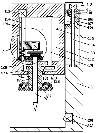
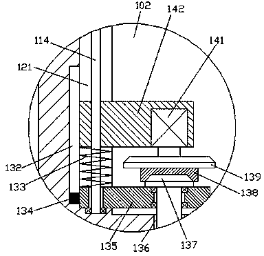
[0016] refer to Figure 1-5 , a new light guide plate assembly device according to an embodiment of the present invention, comprising a support frame 100, an outer shell 122 is provided on the left side of the support frame 100, and a first transmission cavity 123 is arranged inside the outer shell 122, so A rotary cylinder 124 is installed in the bottom wall of the first transmission chamber 123 for rotation. The extension section at the bottom of the rotary cylinder 124 protrudes from the bottom end surface of the outer casing 122 and the bottom end is provided with a grinding device. The top of the rotary cylinder 124 The extension section penetrates into the first transmission cavity 123 and the outer periphery is fixed with a first gear 131, and the drum 124 is provided with a first opening 125 up and down, and a drill bit is installed in the first opening 125 with clearance 126, the o...


PUM


Abstract

The invention discloses a novel light guide plate assembly device which comprises a support frame. An outer shell is arranged on the left side of the support frame. A first conveying cavity is arranged in the outer shell. A rotating barrel is mounted in the bottom wall of the first conveying cavity in a running fit manner. The bottom extending segment of the rotating barrel stretches out of the bottom end face of the outer shell, and a grinding device is arranged at the tail end of the bottom of the rotating barrel. The top extending segment of the rotating barrel penetrates into the first conveying cavity, and a first gear is fixedly arranged on the periphery of the rotating barrel. A first penetrating opening is formed on the rotating barrel in an up-and-down penetrating manner. A drillbit is mounted in the first penetrating opening in a clearance fit manner. A second conveying cavity is arranged at the position, on the upper side of the first conveying cavity, in the outer shell. Asecond penetrating opening opposite to the first penetrating opening is arranged between the second conveying cavity and the first conveying cavity in a communicating manner. The drill is in clearance fit with the second penetrating opening.

Description

technical field [0001] The invention relates to the technical field of light guide plate processing, in particular to a novel light guide plate assembly device. Background technique [0002] At present, after the light guide plate is produced and shaped, it needs to be drilled. After drilling, the outer surface of the light guide plate usually has burrs. At this time, grinding equipment is needed to smooth the burrs. In the prior art Usually, drilling equipment and grinding equipment are used alone, and the light guide plate needs to be repeatedly installed and fixed during adjustment and use. The operation is cumbersome, and the use of the two equipment increases the cost of equipment procurement. All-in-one device with grinding. Contents of the invention [0003] The object of the present invention is to provide a novel light guide plate assembly device for overcoming the above-mentioned defects in the prior art. [0004] A new type of light guide plate assembly device...

Claims


Application Information

Patent Timeline
Patent Type & Authority Applications(China)
IPC IPC(8): B23P23/04
CPCB23P23/04
Inventor 钟奇
Owner 广州创码信息科技有限公司
Why Eureka
Try Eureka