
Inner ring and outer ring synchronous polishing device for automobile bearing

An automobile bearing, inner and outer ring technology, applied in the field of bearing processing, can solve the problem of wasting manpower, material resources and time, and achieve the effect of improving processing efficiency

Inactive Publication Date: 2018-11-13
胡良田
View PDF1 Cites 14 Cited by
  • Summary
  • Abstract
  • Description
  • Claims
  • Application Information

AI Technical Summary

Problems solved by technology

[0004] The technical disadvantage of the above solution is: the device is only aimed at grinding the inner ring of the bearing and how to deal with the waste after grinding, but it does not mention how to grind the outer ring of the bearing. In this case, the inner ring of the bearing and the outer ring If the rings are operated separately, it will be a waste of manpower, material resources and time

Method used


Image

  • Inner ring and outer ring synchronous polishing device for automobile bearing
  • Inner ring and outer ring synchronous polishing device for automobile bearing
  • Inner ring and outer ring synchronous polishing device for automobile bearing

Examples


Embodiment Construction

[0026] Below in conjunction with accompanying drawing and embodiment of description, specific embodiment of the present invention is described in further detail:

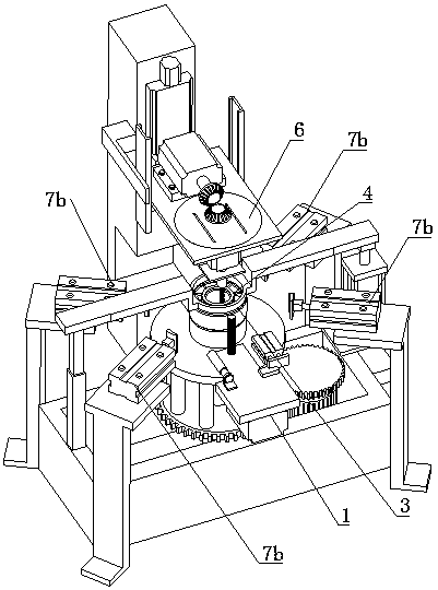
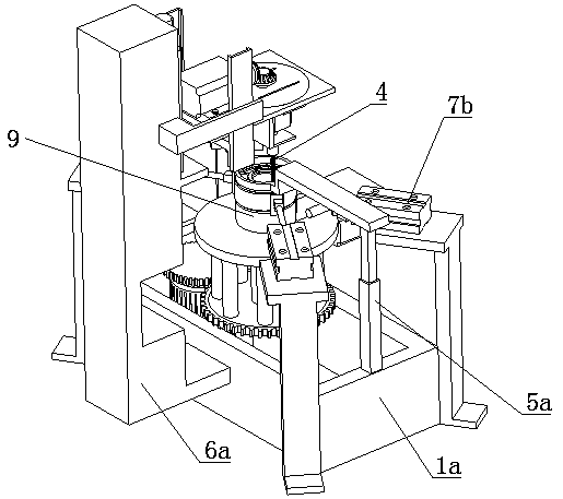
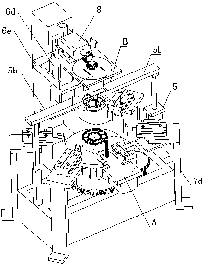
[0027] refer to Figure 1 to Figure 10 The shown synchronous grinding equipment for the inner and outer rings of automobile bearings includes a first grinding device 1 for supporting the bearing 9 and grinding the surface of the outer ring, which is arranged directly above the first grinding device 1 and used for grinding the bearing 9 The second grinding device 6 for grinding the inner ring, and the four limiting components arranged around the first grinding device 1 .

[0028] The first grinding device 1 comprises a vertical processing column 1b, a lower positioning block 3 and an upper positioning block 4 arranged at the top of the processing column 1b, and the upper positioning block 4 can be vertically movable through the avoidance assembly and is arranged on the lower positioning block 3. Directly above, the ...


PUM


Abstract

The invention relates to the field of bearing machining, in particular to an inner ring and outer ring synchronous polishing device for an automobile bearing. The inner ring and the outer ring synchronous polishing device for the automobile bearing comprises a first polishing device, a second polishing device and four limiting assemblies, wherein the first polishing device is used for supporting the bearing and polishing the surface of the outer ring of the bearing, the second polishing device is arranged over the first polishing device and used for polishing the inner ring of the bearing, andthe four limiting assemblies are arranged on the periphery of the first polishing device. The first polishing device comprises a machining column, a lower locating block arranged at the top end of the machining column and an upper locating block. The upper locating block can be arranged over the lower locating block through a receding assembly and is a vertically movable manner. The upper half section of the machining column is sleeved with an edging rotating disk capable of rotating around own axis. The edging rotating disk is provided with an outer ring polishing assembly capable of conducting reciprocating motion in the radial direction of the edging rotating disk. The four limiting assemblies are arranged on the periphery of the edging rotating disk and are symmetrical in pairs. The inner ring and the outer ring synchronous polishing device for the automobile bearing can synchronously polish the inner ring and the outer ring of the bearing and greatly improves the machining efficiency of the bearing and the overall machining yield.

Description

technical field [0001] The invention relates to the field of bearing processing, in particular to a synchronous grinding device for inner and outer rings of automobile bearings. Background technique [0002] Bearing is an important part of contemporary mechanical equipment. Its main function is to support the mechanical rotating body, reduce the friction coefficient during its movement, and ensure its rotation accuracy. According to the different friction properties of moving elements, bearings can be divided into rolling bearings There are two types of sliding bearings, and its accuracy, performance, life and reliability play a decisive role in the accuracy, performance, life and reliability of the host; so after the bearing is manufactured, it is necessary to check the surface of the outer ring and the inner ring Carry out precise grinding work to ensure the effective work of the bearing in the later stage. [0003] In order to solve the above problems, the Chinese patent...

Claims


Application Information

Patent Timeline
Patent Type & Authority Applications(China)
IPC IPC(8): B24B27/00B24B41/06
CPCB24B27/0076B24B27/0092B24B41/06
Inventor 胡良田
Owner 胡良田
Learn More