Stable and safe hammer assembly

A safe and component technology, applied in the field of hand tools, can solve the problems of easy knocking of the hammer head and difficulty in finding nails, etc., to avoid knocking on the hand, prevent knocking and improve safety performance.

Active Publication Date: 2018-11-13
CHINA MCC5 GROUP CORP
View PDF6 Cites 1 Cited by
  • Summary
  • Abstract
  • Description
  • Claims
  • Application Information

AI Technical Summary

Problems solved by technology

[0003] The purpose of the present invention is to provide a stable and safe hammer assembly to solve the problems in the prior art that it is difficult to find nails when nailing nails, and at the same time, the hammer head is easy to damage the user's fingers, so as to facilitate the flexible use of a single nail and prevent The user's hand is knocked and the purpose of reducing potential safety hazards

Method used


Image

  • Stable and safe hammer assembly
  • Stable and safe hammer assembly
  • Stable and safe hammer assembly

Examples


Embodiment 1

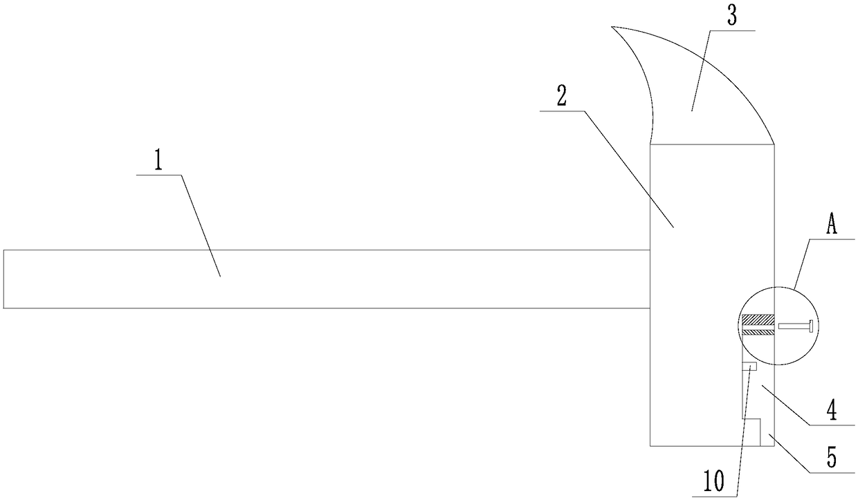
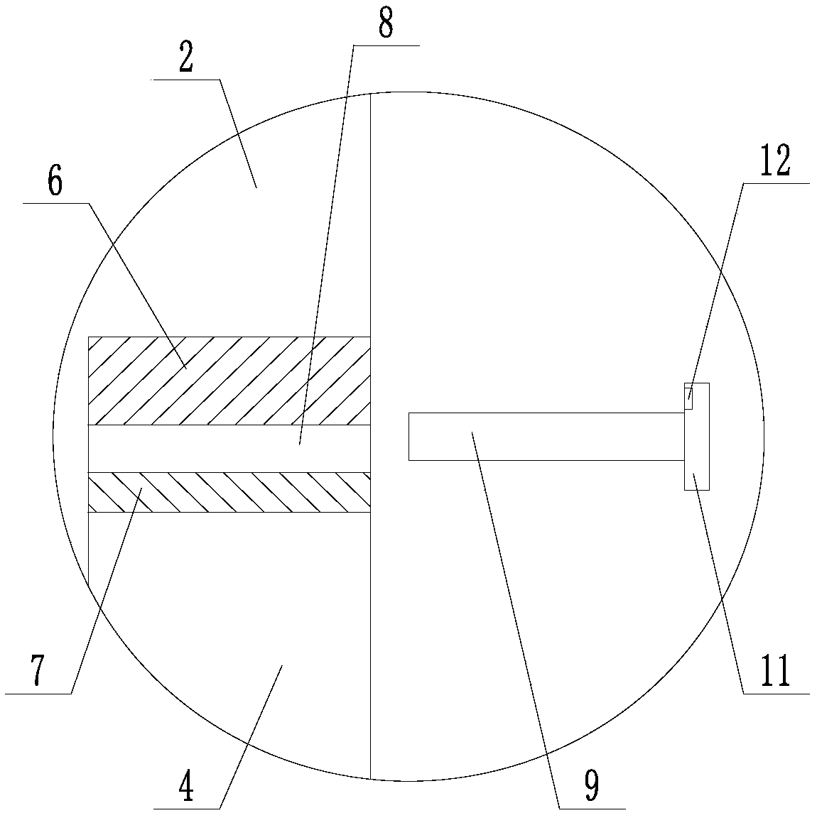
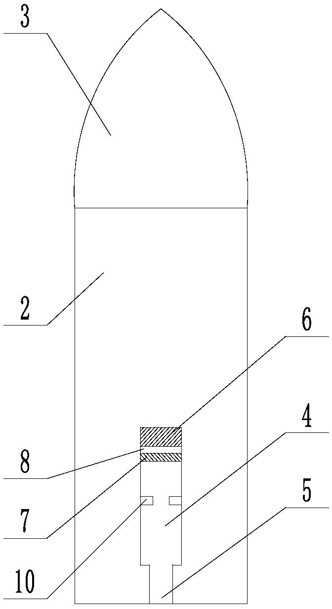
[0033] Such as Figure 1 to Figure 4 A stable and safe hammer assembly shown includes a rod body 1 connected to each other and a hammer head. The hammer head includes an integrally formed flat head 2 and a pointed cone 3. The flat head 2 is square. The side surface of the flat head 2 away from the direction where the rod body 1 is located is the front, and the side surface of the flat head 2 away from the direction where the pointed cone 3 is located is the bottom surface, and the front of the flat head 2 is provided with a first connected to each other. Groove 4, second groove 5, described second groove 5 is positioned between first groove 4 and the bottom surface of flat head 2, and described second groove 5 is open at the bottom surface of described flat head 2 Mouth, the width and depth of the second groove 5 are smaller than the first groove 4; the side wall in the first groove 4 away from the direction where the second groove 5 is fixed permanent magnet plate 6, the firs...

Embodiment 2

[0035] Such as Figure 1 to Figure 5 The shown stable and safe hammer assembly, on the basis of Embodiment 1, also includes an anti-knock assembly, and the anti-knock assembly includes a strip-shaped push plate 13, and one end of the push plate 13 along the long axis direction Two clamping plates 14 are fixedly connected, and the two clamping plates 14 are symmetrical to the long axis of the push plate 13. A clamping seam 15 is formed between the two clamping plates 14, and the clamping seam 15 is along the length of the push plate 13. In the direction of the long axis, the width increases linearly from one end close to the push plate 13 to one end far away from the push plate 13 . The clamping plate 14 is fan-shaped with a central angle of 85°, and one side of the fan-shaped is attached to the side of the push plate 13 . The thickness of the push plate 13 and the clamping plate 14 are equal, and the upper and lower surfaces of the push plate 13 and the clamping plate 14 are ...

Embodiment 3

[0037] Such as Figure 1 to Figure 6 The shown stable and safe hammer assembly, on the basis of Embodiment 2, also includes a mounting block 16 fixed on the upper surface of the push plate 13, the top of the mounting block 16 is provided with a first force transmission plate 17, and the first A force transmission plate 17 is hinged on the top of the mounting block 16 away from the end of the clamping plate 14, and an elastic member 18 is connected between the bottom surface of the first force transmission plate 17 and the top surface of the mounting block 16; The L-shaped piece 19 on the side of the direction of 14, the L-shaped piece 19 is bent upwards, the top of the L-shaped piece 19 is provided with a slider 20, and also includes a driving block 21, and the bottom surface of the driving block 21 is arranged on the same side as the The sliding block 20 matches the sliding rail 22, the sliding block 20 is located in the sliding rail 22, the length direction of the sliding ra...


PUM


Abstract

The invention discloses a stable and safe hammer assembly. A hammerhead comprises a flat head part and a sharp cone part. The front face of the flat head part is provided with a first groove and a second groove which are in mutual communication. The second groove is opened in the bottom face of the flat head part, and the width and the depth of the second groove are smaller than those of the firstgroove. A permanent magnet plate is fixed to the side wall, away from the direction where the second groove is located, of the first groove, the first groove is internally further provided with a magnetic metal plate parallel to the permanent magnet plate, an inserting groove is formed between the permanent magnet plate and the magnetic metal plate, and an isolation plate matched with the inserting groove is further included. The first groove is internally further provided with two right-opposite limiting blocks. The two limiting blocks are connected to the two opposite side walls, adjacent to the second groove, in the first groove correspondingly, and a gap is formed between the two limiting blocks. The stable and safe hammer assembly is used for solving the problems that in the prior art, during nail driving, nails are hard to search, and meanwhile a hammerhead is likely to hurt the fingers of a user during knocking; and the purposes that flexible taking and using of single nails are convenient, meanwhile, knocking hurt of the hand of the user is prevented, and potential safety hazards are reduced are achieved.

Description

technical field [0001] The invention relates to the field of hand tools, in particular to a stable and safe hammer assembly. Background technique [0002] A hammer is a tool for striking an object to move or deform it. Most commonly used for hammering nails, straightening or knocking objects open. Hammers come in a variety of forms, the most common being a handle and top. One side of the top is flat for striking, and the other side is the hammer head. The shape of the hammer head can be like a horn or a wedge, and its function is to pull out nails. It also has a round hammer head. Hammer is a very common hand tool, which is often used in daily life, and basically every household will be equipped with it. Currently, when people use a hammer to knock a nail, they often cannot find the nail, which is not convenient for quick use, and they need to look for suitable nails everywhere. Moreover, in the process of knocking the nails, it is necessary to hold the nails with hand...

Claims


Application Information

Patent Timeline
Patent Type & Authority Applications(China)
IPC IPC(8): B25D1/06
CPCB25D1/06
Inventor 刘建国
Owner CHINA MCC5 GROUP CORP
Why Eureka
Try Eureka